|
 The
x-ray beam spectrum is one of the most critical factors that must be
adjusted to optimize a procedure with respect to contrast sensitivity
and dose. The
x-ray beam spectrum is one of the most critical factors that must be
adjusted to optimize a procedure with respect to contrast sensitivity
and dose.
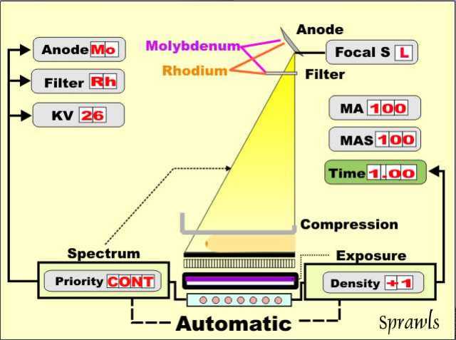
We can think of it as a three-step
procedure:
-
Select the appropriate anode (moly or
rhodium)
-
Select the appropriate filter (moly or
rhodium)
-
Select the appropriate KV (In the range
24 kV to 32 kV)
Increasing the KV has two effects on the
x-ray beam. It increases the efficiency and output for a specific
MAS value and it shifts the photon energy spectrum upward so that the
beam becomes more penetrating.
While a more penetrating beam does reduce
contrast sensitivity it is necessary when imaging thicker and more dense
breast. Therefore compressed breast thickness is the principal
factor that determines the optimum KV.
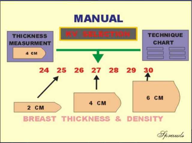
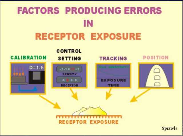
Mammography systems have indicators that
display the thickness of the compressed breast. This along with a
general assessment of breast density is used to manually select
an optimum KV either from experience or an established technique chart.
The general goal is to increase the KV as
necessary to keep the exposure time, MAS, and dose to the breast within
reasonable limits as breast thickness increases.
The automatic selection of the KV is a
design feature of some mammography systems. This is often based on
a short, low-level, "pre-exposure" that is used to measure the
penetration characteristics of the breast. From this, a KV value
is calculated and automatically set for the procedure. Note:
this is combined with the automatic selection of anode and filter
combinations for equipment that has that capability.
The automatic selection of technique
factors is a valuable function because it is based on actual
measurements of breast characteristics. However, it should be used
by experienced radiographers who monitor the selected protocols and
image quality.
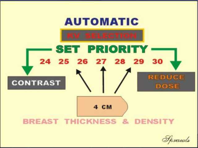
Automatic systems provide an opportunity
for the operator to have some control by setting a "priority" that will
shift the balance between contrast sensitivity and reduced dose.
This function is illustrated here using a 4 cm compressed breast.
If the "contrast" priority or mode is selected the automatic system
would select a relatively low KV value (for example, 25 keV). If
the "dose" mode is set a higher KV value will be selected (for example,
29 keV).
A word of caution....there might
be the temptation to select the "dose" mode with the expectation that it
will reduce the dose to the patient. It will, but at the cost of
reducing contrast sensitivity which might have an adverse effect on the
visibility of some pathologic conditions.
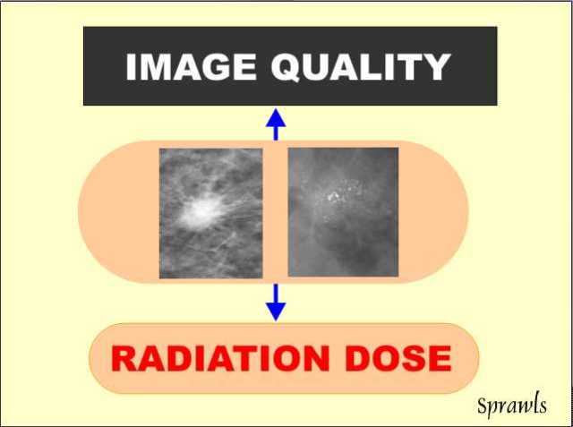
The selection of
technique factors (anode, filter, and KV) to optimize a procedure with
respect to the balance between contrast sensitivity (image quality) and
dose requires an educated and experienced staff.
|

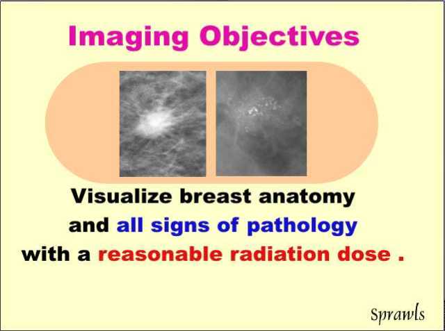 begin with a simple observation that will be a foundation for a much
more in-depth study of the mammography imaging process. We can all agree
on the objectives of the procedure. The challenge is in achieving
the desired results. It begins with the fact that many pathologic
conditions, especially cancer, produce very small
physical changes that are difficult to visualize with x-ray
imaging.
begin with a simple observation that will be a foundation for a much
more in-depth study of the mammography imaging process. We can all agree
on the objectives of the procedure. The challenge is in achieving
the desired results. It begins with the fact that many pathologic
conditions, especially cancer, produce very small
physical changes that are difficult to visualize with x-ray
imaging.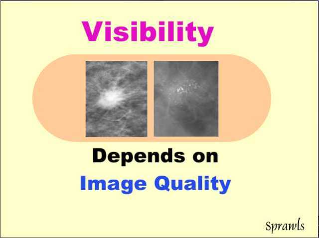 Saying
that visibility of pathologic conditions depends on image quality sounds
like a "no Deterrent." It is a simple point but the complexity comes from
the combined factors that the various signs of pathology have very
different physical characteristics and that image quality is not one,
but a combination of several specific image characteristics.
Saying
that visibility of pathologic conditions depends on image quality sounds
like a "no Deterrent." It is a simple point but the complexity comes from
the combined factors that the various signs of pathology have very
different physical characteristics and that image quality is not one,
but a combination of several specific image characteristics.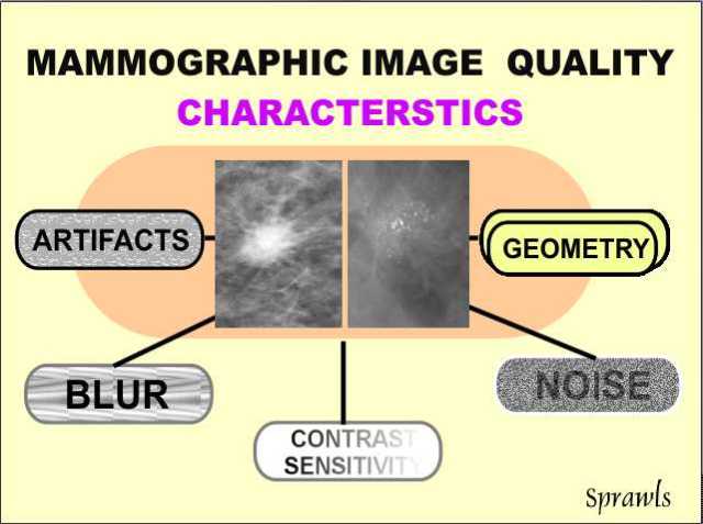 The
quality of a mammogram (just like any other medical image) is not one
single characteristic. It is a composite of five very specific
characteristics as we see here.
The
quality of a mammogram (just like any other medical image) is not one
single characteristic. It is a composite of five very specific
characteristics as we see here.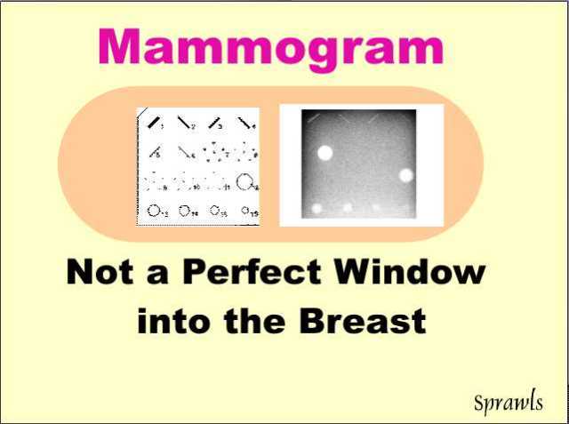 Although
a mammogram is overall probably the highest quality x-ray image we
produce, it is still not perfect, and we cannot assume that it will show
all significant features within a breast.
Although
a mammogram is overall probably the highest quality x-ray image we
produce, it is still not perfect, and we cannot assume that it will show
all significant features within a breast.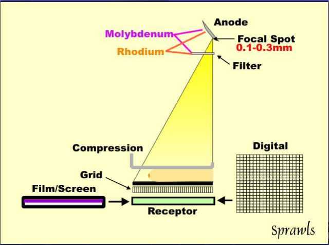
 Optimizing
a mammography procedure for maximum visualization of anatomy and signs
of pathology without unnecessary radiation to the patient is achieved by
the selection of the best combination of technique factors that make up
the imaging protocol.
Optimizing
a mammography procedure for maximum visualization of anatomy and signs
of pathology without unnecessary radiation to the patient is achieved by
the selection of the best combination of technique factors that make up
the imaging protocol.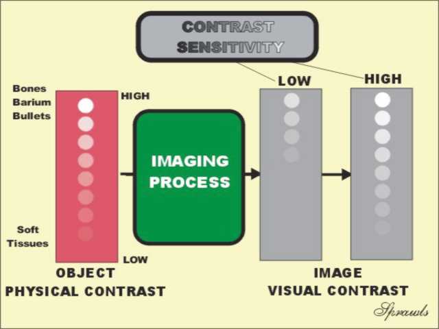 A
major requirement for effective mammography is high contrast
sensitivity. As illustrated here, contrast sensitivity is the
characteristic of an imaging process that determines the visibility of
objects in the body that have low physical contrast. That is the
challenge we have in mammography. The anatomical structures and
pathologic signs are all soft tissues with physical densities very
similar to the adipose background of the breast. The visibility of
small calcifications is limited by blurring and will be discussed
later, but they also require a high contrast sensitivity.
A
major requirement for effective mammography is high contrast
sensitivity. As illustrated here, contrast sensitivity is the
characteristic of an imaging process that determines the visibility of
objects in the body that have low physical contrast. That is the
challenge we have in mammography. The anatomical structures and
pathologic signs are all soft tissues with physical densities very
similar to the adipose background of the breast. The visibility of
small calcifications is limited by blurring and will be discussed
later, but they also require a high contrast sensitivity.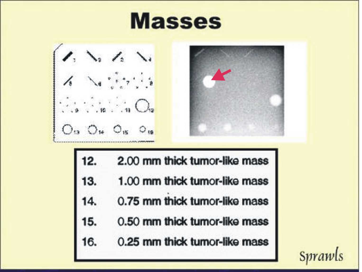
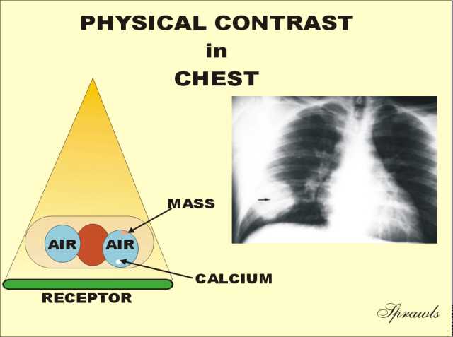
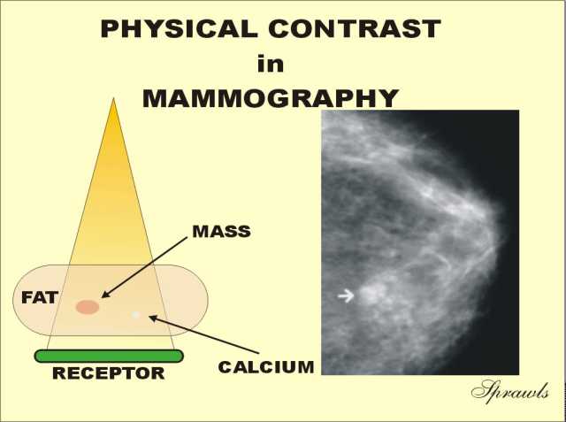 The
breast is the complete opposite to the chest with respect to contrast.
It consist ofs soft tissues with relatively small differences in density
(or atomic number).
The
breast is the complete opposite to the chest with respect to contrast.
It consist ofs soft tissues with relatively small differences in density
(or atomic number).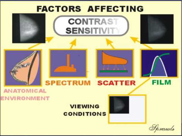 The
breast imaging process consists of a sequence of actions and events
transferring the physical contrast in the breast to visible contrast in
the displayed image. There are factors associated with each of
these that have an effect on contrast sensitivity. We will
introduce them here and then go into more detail as we work through the
imaging process.
The
breast imaging process consists of a sequence of actions and events
transferring the physical contrast in the breast to visible contrast in
the displayed image. There are factors associated with each of
these that have an effect on contrast sensitivity. We will
introduce them here and then go into more detail as we work through the
imaging process. 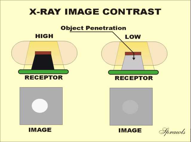
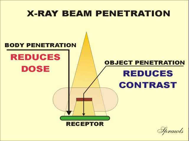 Generally we want maximum penetration through the breast for two
reasons. With good penetration less radiation is required into the
breast to produce the desired receptor exposure. This reduces the
amount of radiation and heat that must be produced by the x-ray
tube for each exposure. The benefit is that the exposure times can
be kept relatively short to reduce motion blurring (a problem especially
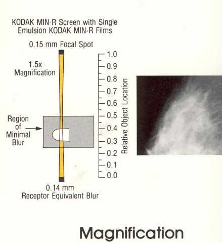
with large breasts) and less heat is produced in the focal spot area.
This is a potential limiting factor when using the small focal spot for
the magnification technique.
Generally we want maximum penetration through the breast for two
reasons. With good penetration less radiation is required into the
breast to produce the desired receptor exposure. This reduces the
amount of radiation and heat that must be produced by the x-ray
tube for each exposure. The benefit is that the exposure times can
be kept relatively short to reduce motion blurring (a problem especially
with large breasts) and less heat is produced in the focal spot area.
This is a potential limiting factor when using the small focal spot for
the magnification technique.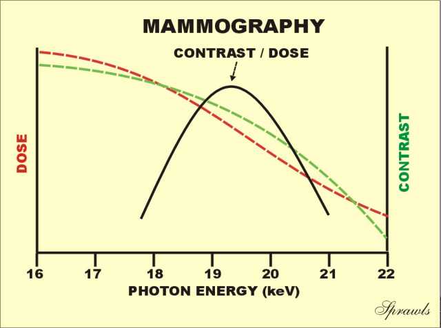
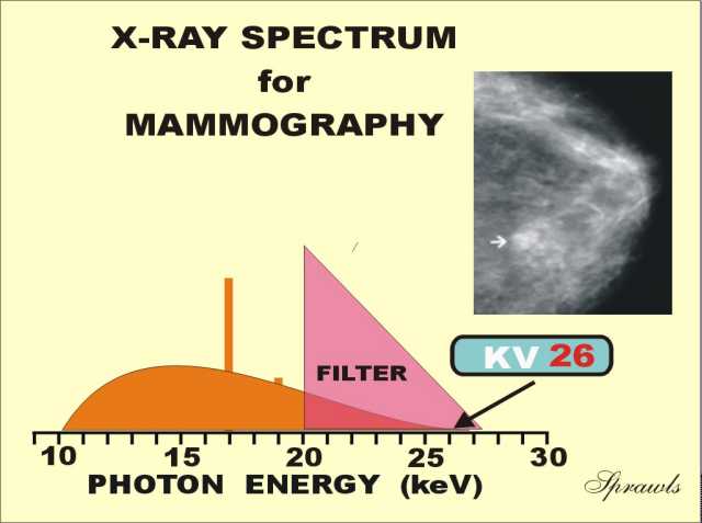
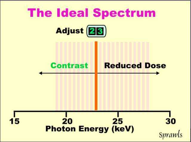
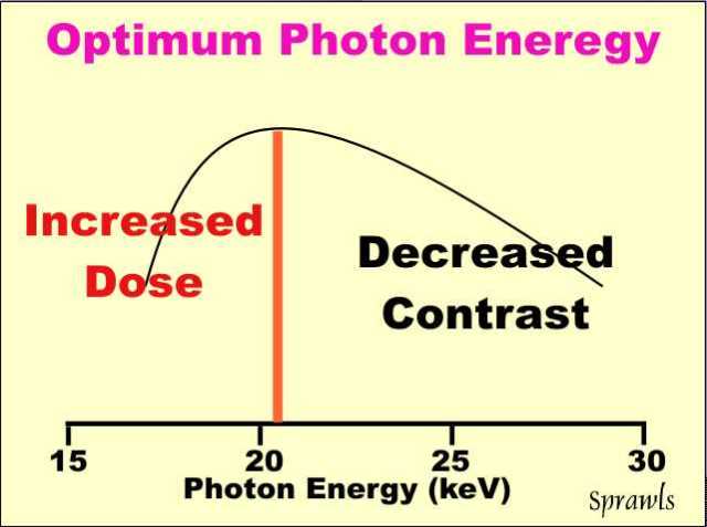 The
ideal or "perfect" x-ray spectrum for mammography would be made up of
photons all having the same energy (mono-energetic) and with the ability
to adjust the energy for different breast conditions. That is
represented by the vertical line
shown here positioned at the optimum energy for this particular breast.
The
ideal or "perfect" x-ray spectrum for mammography would be made up of
photons all having the same energy (mono-energetic) and with the ability
to adjust the energy for different breast conditions. That is
represented by the vertical line
shown here positioned at the optimum energy for this particular breast.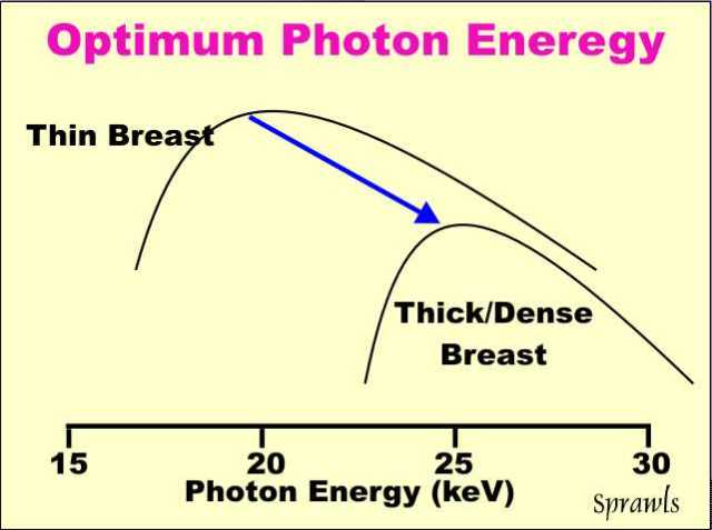 The
optimum photon energy (spectrum) for mammography depends on the size and
density of the breast.
The
optimum photon energy (spectrum) for mammography depends on the size and
density of the breast.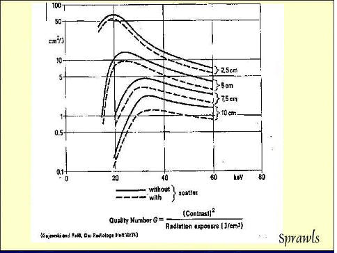
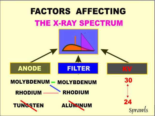 The
x-ray spectrum is determined by a combination of three (3) factors:
The
x-ray spectrum is determined by a combination of three (3) factors:
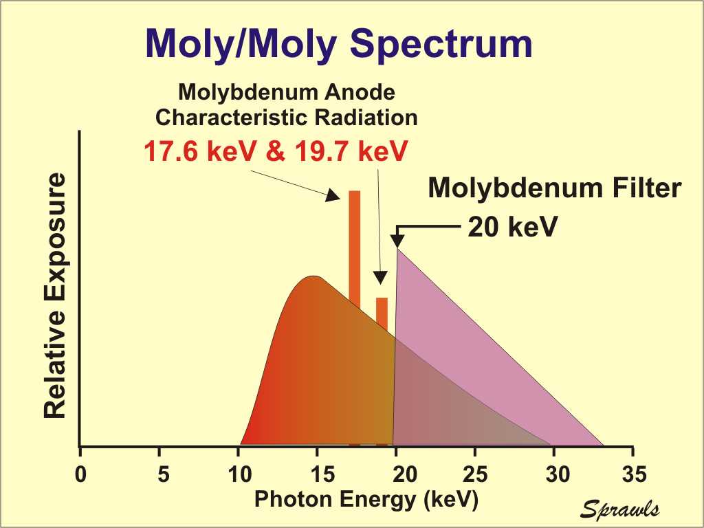 Here
we see the molybdenum spectrum in more detail showing both the
characteristic radiation and the bremsstrahlung.
Here
we see the molybdenum spectrum in more detail showing both the
characteristic radiation and the bremsstrahlung.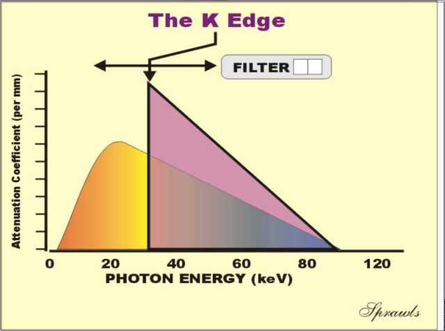 The
next step to produce an optimized spectrum is to use a filter to
attenuate or block that part of the bremsstrahlung that is above the
desired energy range. That is achieved with filters based on the "k
edge" principle.
The
next step to produce an optimized spectrum is to use a filter to
attenuate or block that part of the bremsstrahlung that is above the
desired energy range. That is achieved with filters based on the "k
edge" principle.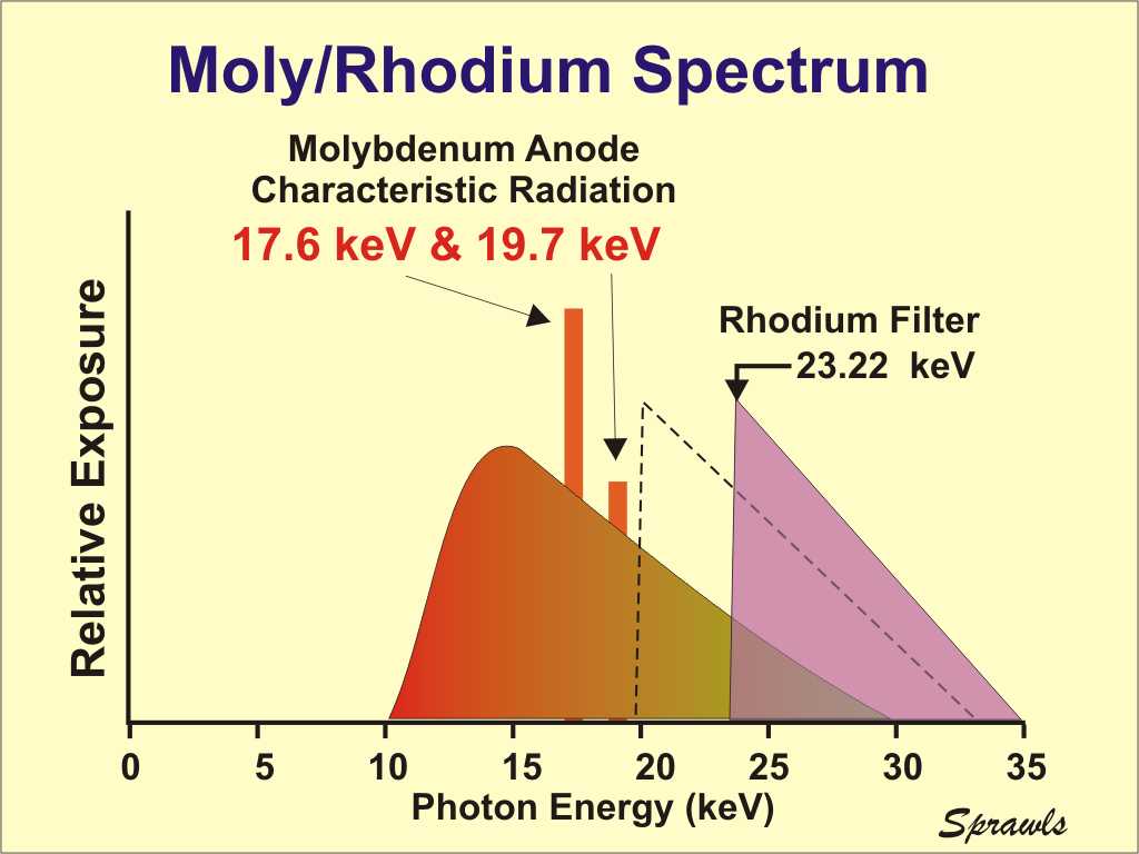
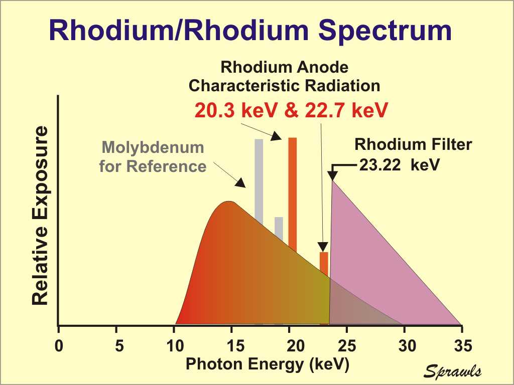 Rhodium is an alternative anode material that can be
selected to produce a more penetrating x-ray beam than the more
conventional molybdenum anode. It is available in some mammography
systems in the form of a dual-track (molybdenum and rhodium) x-ray tube
anode. The operator or AEC selects the one that is optimum for a
specific patient based on breast characteristics, especially density.
Rhodium is an alternative anode material that can be
selected to produce a more penetrating x-ray beam than the more
conventional molybdenum anode. It is available in some mammography
systems in the form of a dual-track (molybdenum and rhodium) x-ray tube
anode. The operator or AEC selects the one that is optimum for a
specific patient based on breast characteristics, especially density.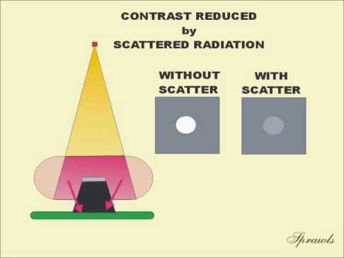 Even
though a breast is relatively small compared to most of the body, it is
still the source of significant scattered radiation that reduces
contrast as illustrated This must be considered because in
mammography we are attempting to see many low contrast structures where
any reduction in contrast can be detrimental.
Even
though a breast is relatively small compared to most of the body, it is
still the source of significant scattered radiation that reduces
contrast as illustrated This must be considered because in
mammography we are attempting to see many low contrast structures where
any reduction in contrast can be detrimental.
 As
the x-ray beam exits the breast it contains an image in the form of
different levels of exposure produced by the variation in penetration
through the different densities that make up the physical contrast.
As
the x-ray beam exits the breast it contains an image in the form of
different levels of exposure produced by the variation in penetration
through the different densities that make up the physical contrast.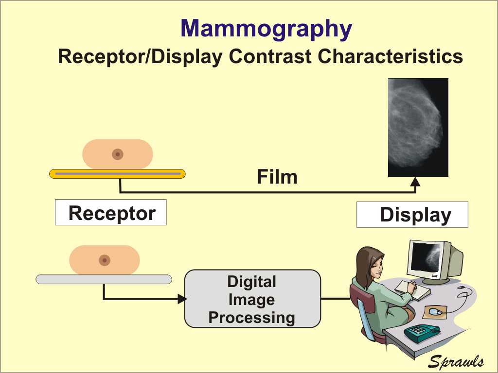 There
are two very different methods for recording and displaying mammograms:
film and digital.
There
are two very different methods for recording and displaying mammograms:
film and digital.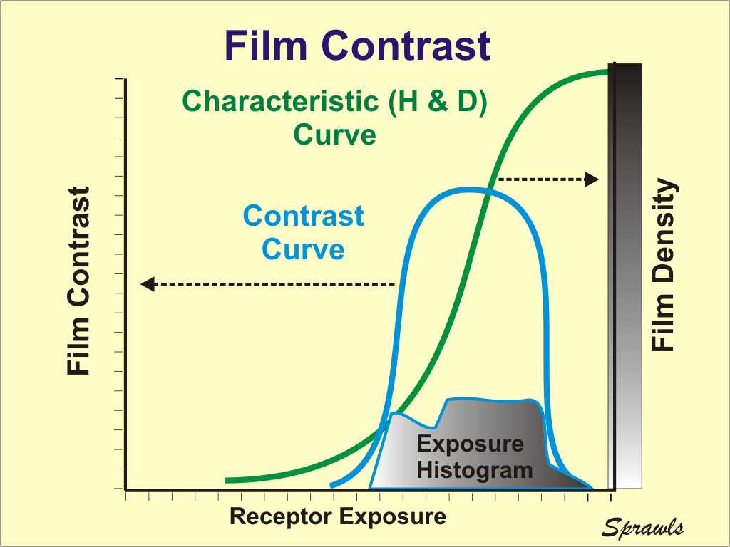
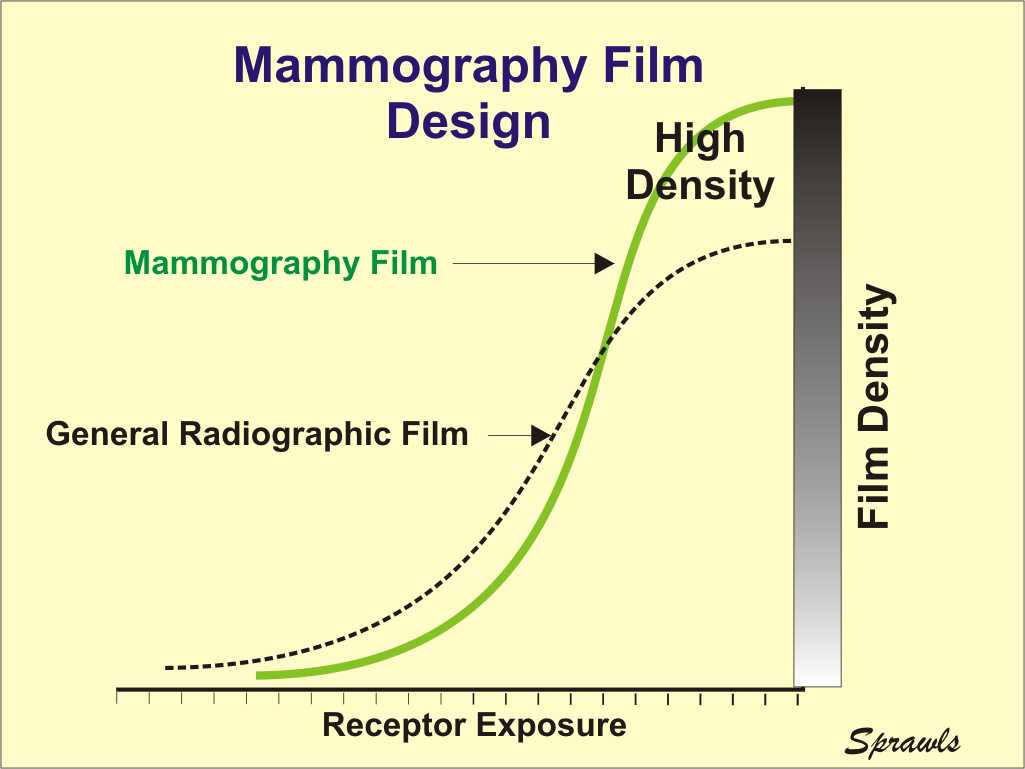 For mammography we need two film
characteristics that generally are conflicting with each other.
First, we need a steep characteristic curve because that represents high
contrast transfer and contrast sensitivity. However, for the usual
range of film densities that can be viewed on a conventional viewbox, a
steep characteristic curve results in a reduced latitude. A wide
latitude is required to image the rather wide range of exposure coming
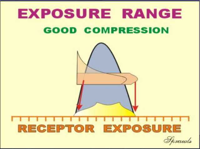
through the breast. While compression is useful in providing a more
uniform breast thickness, and a smaller range of exposure, there is
still a considerable range because of other variations in thickness
(near the nipple) and in density.
For mammography we need two film
characteristics that generally are conflicting with each other.
First, we need a steep characteristic curve because that represents high
contrast transfer and contrast sensitivity. However, for the usual
range of film densities that can be viewed on a conventional viewbox, a
steep characteristic curve results in a reduced latitude. A wide
latitude is required to image the rather wide range of exposure coming
through the breast. While compression is useful in providing a more
uniform breast thickness, and a smaller range of exposure, there is
still a considerable range because of other variations in thickness
(near the nipple) and in density. 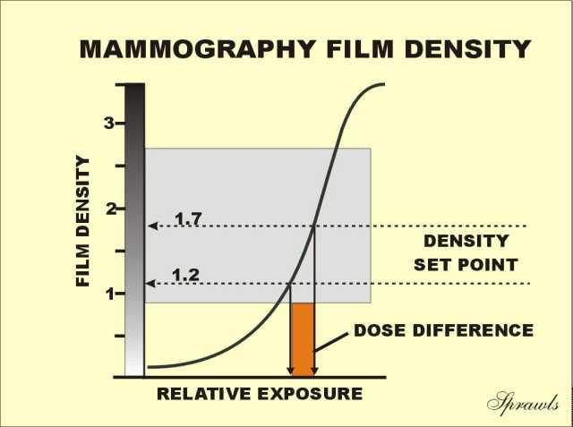
 Most
mammograms are made using Automatic Exposure Control (AEC). The
AEC system measures the exposure that reaches the receptor after
penetrating the breast and turns the exposure off when the necessary
exposure has been delivered to produce the expected film density.
Most
mammograms are made using Automatic Exposure Control (AEC). The
AEC system measures the exposure that reaches the receptor after
penetrating the breast and turns the exposure off when the necessary
exposure has been delivered to produce the expected film density.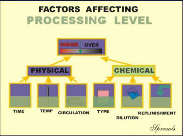 latent image and then the film is chemically processed to develop the
visible image.
latent image and then the film is chemically processed to develop the
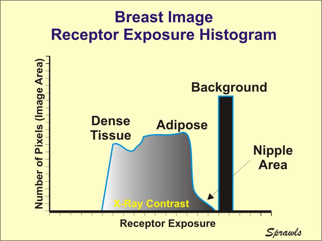
visible image.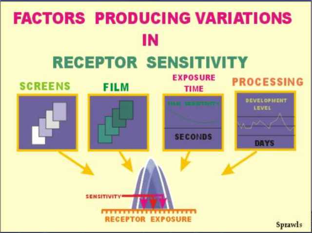 Maximum
contrast and visibility is obtained when the receptor exposure,
represented by the histogram, is positioned under the contrast curve
(within the film latitude or dynamic range).
Maximum
contrast and visibility is obtained when the receptor exposure,
represented by the histogram, is positioned under the contrast curve
(within the film latitude or dynamic range).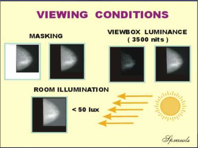 The
display and viewing of the film is the last step in the total process of
visualizing the anatomy and pathology within the breast.
The
display and viewing of the film is the last step in the total process of
visualizing the anatomy and pathology within the breast.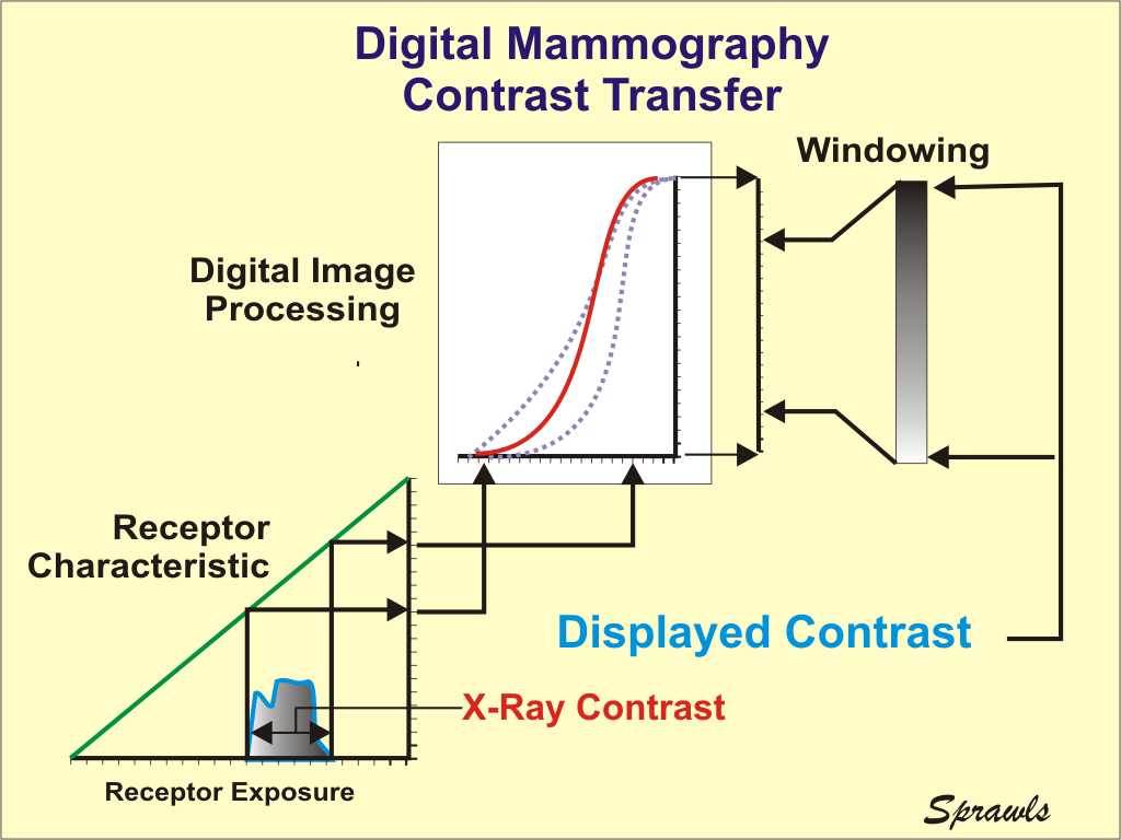 Digital
mammography provides several advantages over film for optimizing the
contrast transfer from the breast to the image display and the
maximizing the overall contrast sensitivity.
Digital
mammography provides several advantages over film for optimizing the
contrast transfer from the breast to the image display and the
maximizing the overall contrast sensitivity.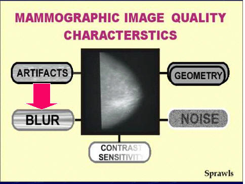
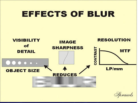 There
are three (3) observable effects of blur that we will review here.
There
are three (3) observable effects of blur that we will review here.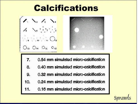 visibility
of detail (effect of blurring) is routinely measured in mammography by
imaging the accreditation phantom introduced earlier and shown again
here.
visibility
of detail (effect of blurring) is routinely measured in mammography by
imaging the accreditation phantom introduced earlier and shown again
here.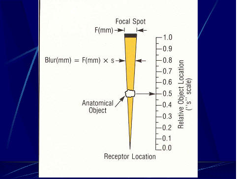 The
blurring produced by the focal spot depends on two factors:
The
blurring produced by the focal spot depends on two factors: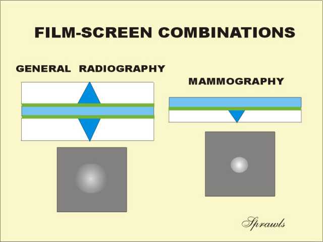
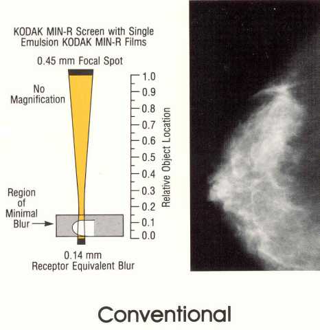
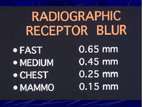 The
dimensions of the blur produced within a receptor is generally related
to thickness and is a tradeoff with x-ray absorption and patient
exposure.
The
dimensions of the blur produced within a receptor is generally related
to thickness and is a tradeoff with x-ray absorption and patient
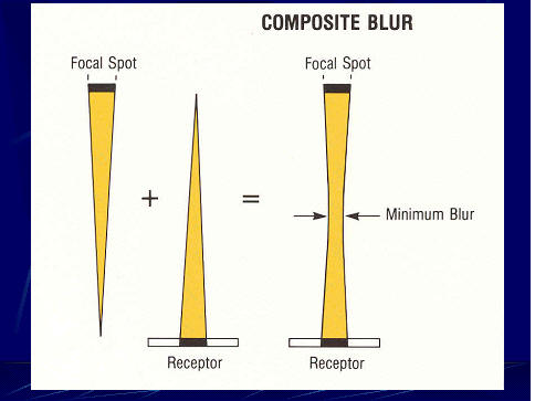
exposure.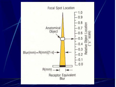 The
significance of blurring, and its effect on visibility, depends on the
amount of blurring at the location of the object (think calcification
again) within the space between the receptor and focal spot as shown
here.
The
significance of blurring, and its effect on visibility, depends on the
amount of blurring at the location of the object (think calcification
again) within the space between the receptor and focal spot as shown
here.