How to Use This Resource
Table of Contents and List of Topics
Outline
Mind Map
Learning Objectives
Online Module
Text Reference
Visuals For The Classroom
To begin classroom presentation CLICK HERE
1
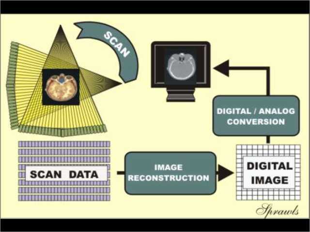
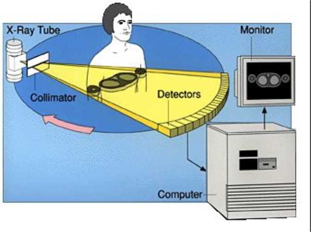
The three phases of CT image formation.
BACK
NEXT
2
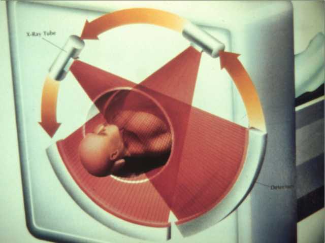
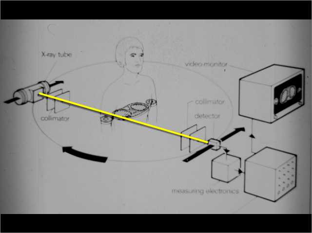
The x-ray tube scanning around the patient's body.
3
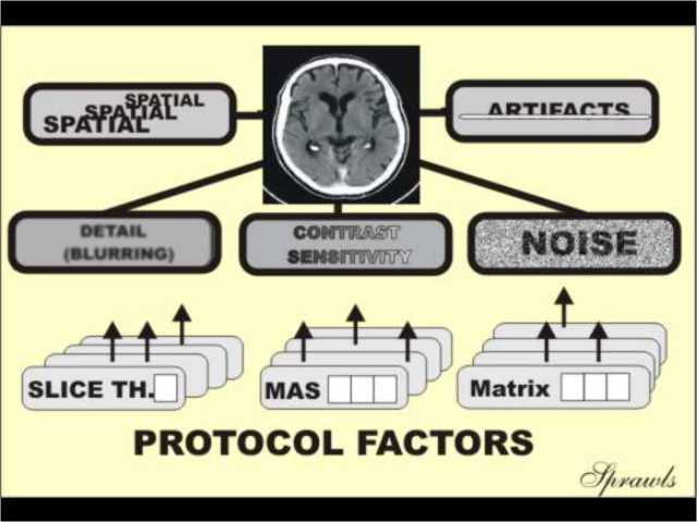
The image quality characteristics of a CT image.
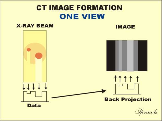
4
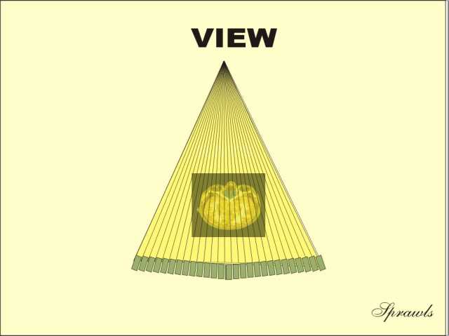
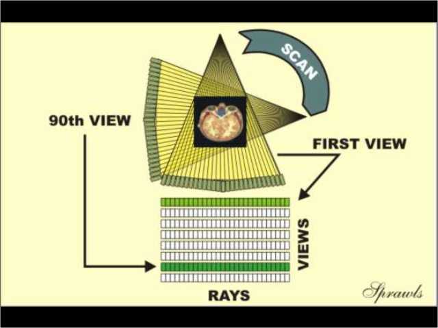
A VIEW produced from one x-ray tube position.
5
A CT system showing one VIEW.
6
One RAY within a VIEW.
7
A SCAN is made up of many VIEWS.
8
A SCAN produces a DATA SET that will later be used to reconstruct an image.
9
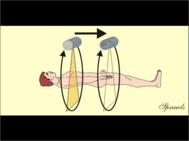
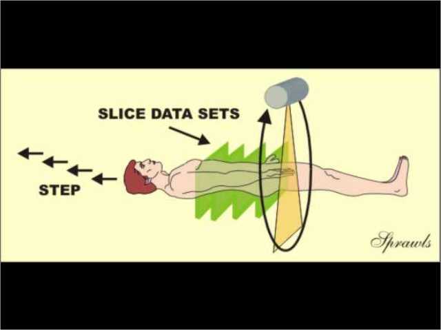
The x-ray beam is moved along the patient's body to produce images of more slices.
10
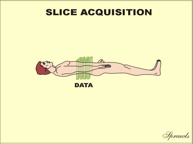
The scan-and-step method produces data sets for individual slices.
11
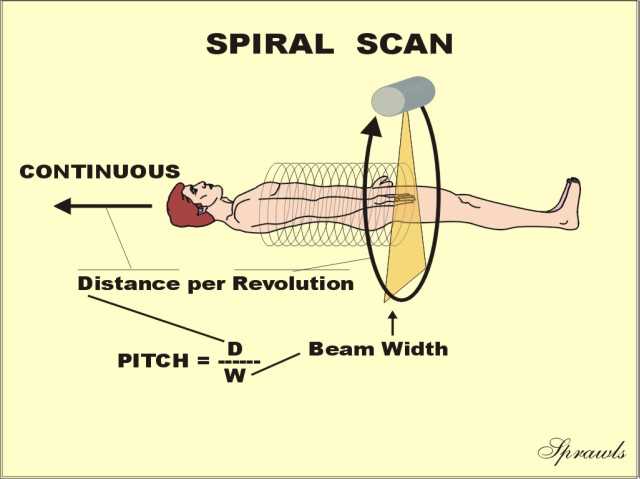
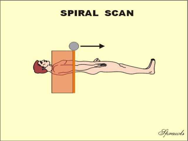
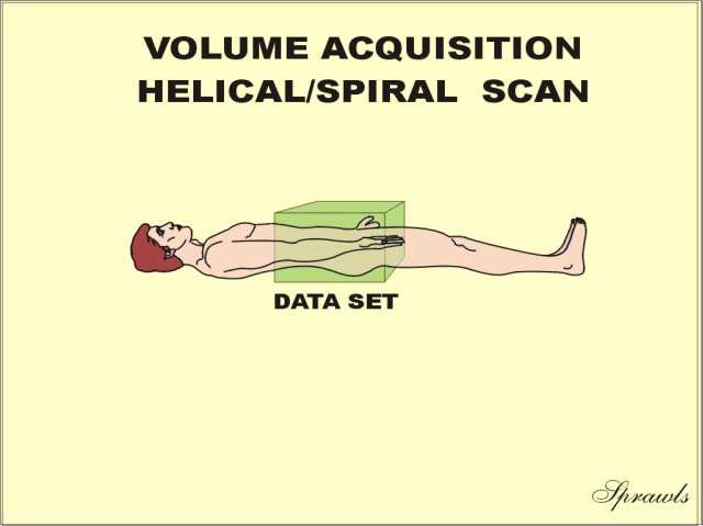
Spiral (helical) scanning moves the body continuously through the beam.
12
This is what we see if we move along with the patient.
13
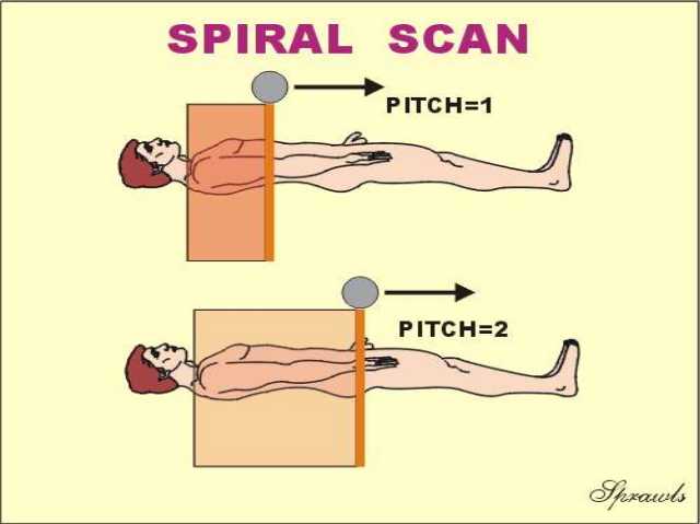
Increasing the PITCH moves the body faster through the beam.
14
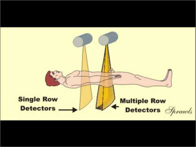
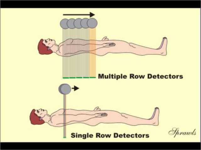
CT machines can have either single or multiple rows of detectors.
15
Multiple-row detectors scan faster.
16
Helical/spiral scanning produces a continuous data set.
17
Scan-and-step slice acquisition produces data sets for individual slices.
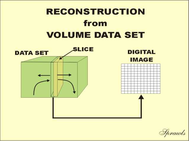
18
Images can be reconstructed from any slice location within a volume data set.
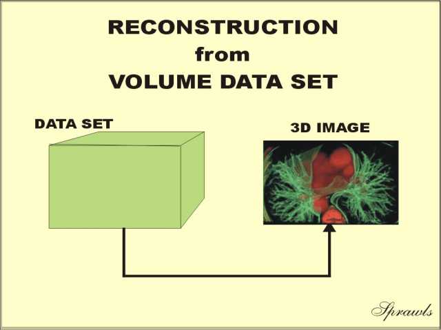
19
3D images can be reconstructed from volume data sets.
20
21
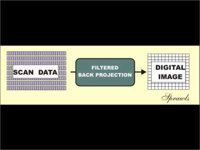
The FILTERED BACK PROJECTION method reconstructs an image from the scan data.
22
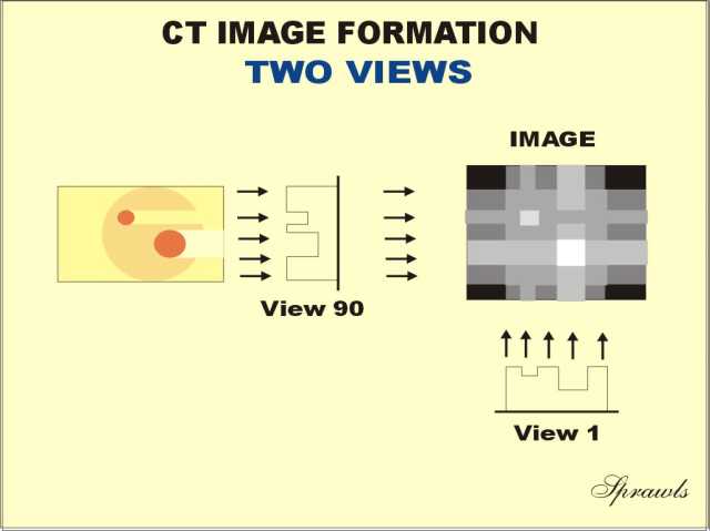
An image reconstructed from one view.
23
The image is improved with two views.
24
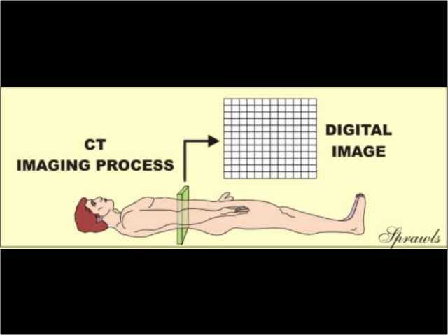
The reconstruction process divides the slice of tissue into voxels that correspond to image pixels.
25
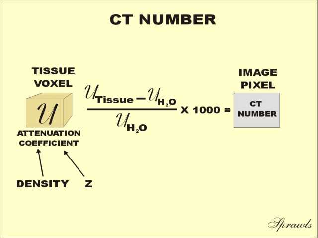
A CT NUMBER is calculated for each voxel/pixel during the reconstruction process.
26
27
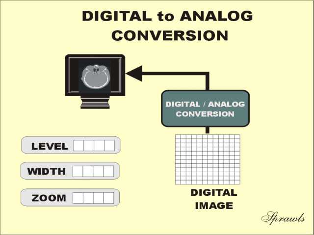
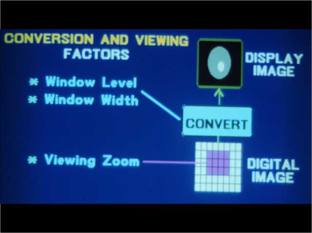
The DIGITAL-TO-ANALOG conversion is the last phase.
28
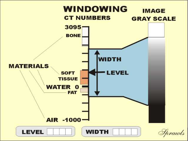
Window LEVEL and WIDTH must be set to view specific tissues.
29
Windowing contributes to the high contrast sensitivity of CT.
30
ZOOM is the process of selecting a smaller area within the reconstructed image for display.
The End
31
To return to the beginning, CLICK HERE.