
Chapter 9
|
|
Chapter 9 |
| Link to Book Table of Contents | Chapter Contents Shown Below |
The MR image formation process subdivides a section of the patient’s body into a set of slices and then each slice is cut into rows and columns to form a matrix of individual tissue voxels. This was introduced first in Chapter 1 and illustrated in Figure 1-3. The RF signal from each individual voxel must be separated from all of the other voxels and its intensity displayed in the corresponding image pixel, as shown in Figure 9-1.
|
Figure 9-1. The relationship of tissue
voxels to image pixels. |
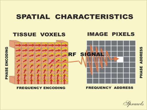 |
This
is achieved by encoding or addressing the signals during the acquisition phase
and then, in effect, delivering the signal intensities to the appropriate pixels
which have addresses within the image during the reconstruction phase. Because
there are two dimensions, or directions, in an image, two different methods of
encoding must be used. This is analogous to mail that must have both a street
name and a house number in the address. We are about to see that the two methods
of addressing the signals are called frequency-encoding and
phase-encoding. One method is applied to one direction in the image and the
other method is used to address in the other direction.
This two-step process consisting of the signal acquisition phase followed by the image reconstruction phase is illustrated in Figure 9-2.
|
Figure 9-2. The two phases—signal acquisition and image
reconstruction —that are required to produce an MR image. |
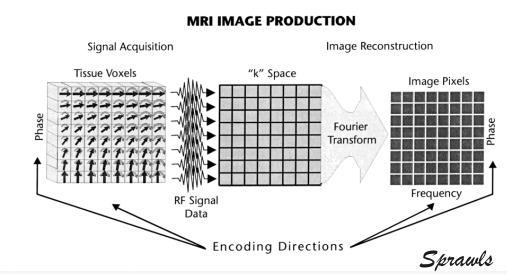 |
Different
actions happen in these two phases that must be considered when setting up an
imaging procedure.
During
the acquisition phase the RF signals are emitted by the tissue and received by
the RF coils of the equipment. During this process the signals from the
different slices and voxels are given distinctive frequency and phase
characteristics so that they can be separated from the other signals during
image reconstruction. The acquisition phase consists of an imaging cycle that is
repeated many times. The time required for image acquisition is determined by
the time TR, which is the duration of one cycle or its repetition time, and the
number of cycle repetitions. The number of cycles is determined by the image
quality requirements. In general, the quality of an image can be improved by
increasing the number of acquisition cycles. This is considered in much more
detail in Chapter 10.
The result of the image acquisition process is a large amount of data
collected and stored in computer memory. At this point the data represent RF
signal intensities characterized by the two characteristics, frequency
and phase. The concept of frequency and phase will be developed later. At
this point in the process the data are not yet in the form of an image but are
located in k space. The data will later be transformed into image space by the
reconstruction process.
Image
reconstruction is a mathematical process performed by the computer. It
transforms the data collected during the acquisition phase into an image. We can
think of reconstruction as the process of sorting the signals collected during
the acquisition and then delivering them to the appropriate image pixels. The
mathematical process used is known as Fourier transformation. Image
reconstruction is typically much faster than image acquisition and requires very
little, if any, control by the user.
The most
significant spatial characteristic of an image is the size of the individual
tissue voxels. Voxel size has a major effect on both the detail and noise
characteristics of the image. The user can select the desired voxel size by
adjusting a combination of imaging factors, as described in Chapter 10.
The
spatial characteristics of an MR image are produced by actions of the gradients
applied during the acquisition phase. Magnetic field gradients are used first to
select slices and then give the RF signals the frequency and phase
characteristics that create the individual voxels.
As we will see later, a gradient in one direction is used to create the
slices, and then gradients in the other directions are used to cut the slices
into rows and columns to create the individual voxels. However, these functions
can be interchanged or shared among the different gradient coils to permit
imaging in any plane through the patient’s body.
The functions performed by the various gradients usually occur in a
specific sequence. During each individual image acquisition cycle the various
gradients will be turned on and off at specific times. As we will see later, the
gradients are synchronized with other events such as the application of the RF
pulses and the acquisition of the RF signals.
There
are two distinct methods used to create the individual slices. The method of
selective excitation actually creates the slice during the acquisition
phase. An alternative method is to acquire signals from a large volume of tissue
(like an organ) and then create the slices during the reconstruction process.
These are often referred to as 2-D (volume) and 3-D (volume) acquisitions.
However, each produces data that are reconstructed into slice images. Both
methods have advantages and disadvantages, which will be described later.
The
first gradient action in a cycle defines the location and thickness of the
tissue slice to be imaged. We will illustrate the procedure for a conventional
transaxial slice orientation. Other orientations, such as sagittal, coronal, and
angled combinations, are created by interchanging and combining gradient
directions.
Slice selection using the principle of selective excitation is illustrated in Figure 9-3.
|
Figure 9-3. The use of
a gradient to tune a specific slice so that it can be selectively
excited by an RF pulse. |
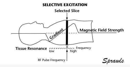 |
When a
magnetic field gradient is oriented along the patient axis, each slice of tissue
is in a different field strength and is tuned to a different resonant frequency.
Remember, this is because the resonant frequency of protons is directly
proportional to the strength of the magnetic field at the point where they are
located. This slice selection gradient is present whenever RF pulses are applied
to the body. Since RF pulses contain frequencies within a limited range (or
bandwidth), they can excite tissue only in a specific slice. The location of the
slice can be changed or moved along the gradient by using a slightly different
RF pulse frequency. The thickness of the slice is determined by a combination of
two factors: (1) the strength, or steepness, of the gradient, and (2) the range
of frequencies, or bandwidth, in the RF pulse.
In most clinical applications, it is desirable to have a series of images (slices) covering a specific anatomical region. By using the multi-slice mode, an entire set of images can be acquired simultaneously. The basic principle is illustrated in Figure 9-4.
| Figure 9-4. Multiple slice imaging applies pulses to and produces signals from different slices within one imaging cycle |
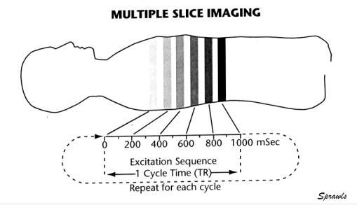 |
The
slices are separated by applying the RF pulses and detecting the signals from
the different slices at different times, in sequence, during each imaging cycle.
When the slice selection gradient is turned on, each slice is tuned to a
different resonant frequency. A specific slice can be selected for excitation by
adjusting the RF pulse frequency to correspond to the resonant frequency of that
slice. The process begins by applying an excitation pulse to one slice and
collecting the echo signal. Then, while that slice undergoes longitudinal
relaxation before the next cycle can begin, the excitation pulse frequency is
shifted to excite another slice. This process is repeated to excite and collect
signals from the entire set of slices at slightly different times within one TR
interval.
The advantage of multi-slice imaging is that a set of slices can be
imaged in the same time as a single slice. The principal factor that limits the
number of slices is the value of TR. It takes a certain amount of time to excite
and then collect the signals from each slice. The maximum number of slices is
the TR value divided by the time required for each slice. This limitation is
especially significant for T1-weighted images that use relatively short TR
values.
A factor to consider when selecting the slicing mode is that multiple
slice selective excitation cannot produce the contiguous slices that the volume
acquisition technique can. With selective excitation there is the possibility
that when an RF excitation/saturation pulse is applied to one slice of tissue,
it will also produce some effect in an adjacent slice. This is a reason for
leaving gaps between slices during the acquisition.
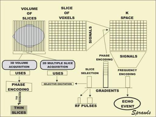
Volume (3-D) image acquisition has the advantage of being able to produce thinner and more contiguous slices. This is because of the process used to slice the tissue. Rather than producing each slice during the acquisition phase, the slicing is done during the reconstruction phase using the process of phase-encoding. The actual process of phase-encoding will be described later in this chapter. At this time we only consider how it is used for slicing. With this method, no gradient is present when the RF pulse is applied to the tissue. Since all tissue within an anatomical region, such as the head, is tuned to the same resonant frequency, all tissues are excited simultaneously. The next step, as illustrated in Figure 9-5,
| Figure 9-5. The 3-D volume acquisition process uses the phase-encoding process to produce thin slices. |
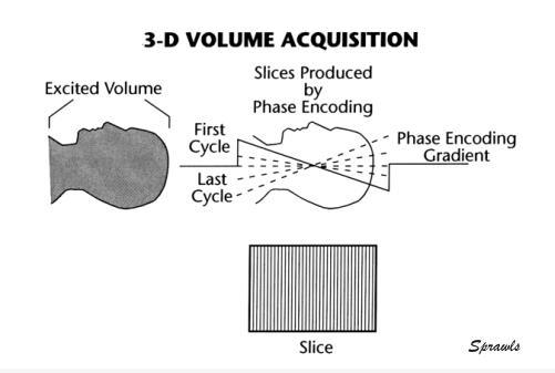 |
is
to apply a phase-encoding gradient in the slice selection direction. In volume
imaging, phase-encoding is used to create the slices in addition to creating the
voxel rows as described below. The phase-encoding gradient used to define the
slices must be stepped through different values, corresponding to the number of
slices to be created. At each gradient setting, a complete set of imaging cycles
must be executed. Therefore, the total number of cycles required in one
acquisition is multiplied by the number of slices to be produced. This has the
disadvantage of causing 3-D volume acquisitions to have a relatively long
acquisition time compared to 2-D multiple slice acquisitions. That is why this
type of acquisition is often used with one of the faster imaging methods.
The primary advantage of volume imaging is that the phase-encoding
process can generally produce thinner and more contiguous slices than the
selective excitation process used in 2-D slice acquisition. The primary
disadvantage is longer acquisition times.
A
fundamental characteristic of an RF signal is its frequency. Frequency is the
number of cycles per second of the oscillating signal. The frequency unit of
Hertz (Hz) corresponds to one cycle per second. Radio broadcast stations
transmit signals on their assigned frequency. By tuning our radio receiver to a
specific frequency we can select and separate from all other signals the
specific broadcast we want to receive. In other words, the radio broadcasts from
all of the stations in a city are frequency encoded. The same process
(frequency-encoding) is used to cause voxels to produce signals that are
different and can be used to create one dimension of the image.
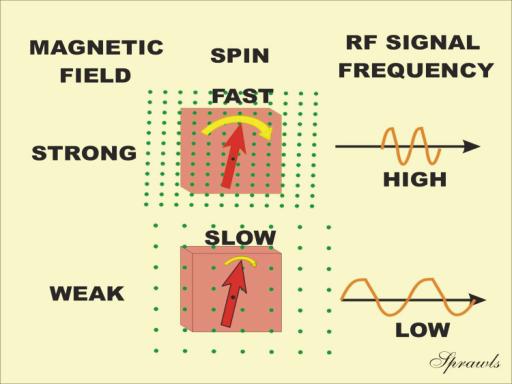
Let us review the concept of RF signal production by voxels of tissue, as shown in Figure 9-6.
|
Figure 9-6. The effect
of field strength on the frequency of RF signals produced by transverse
magnetization. |
 |
RF
signals are produced only when transverse magnetization is present. The unique
characteristic of transverse magnetization that produces the signal is a
spinning magnetic effect, as shown. The transverse magnetization spins around
the axis of the magnetic field. A spinning magnet or magnetization in the
vicinity of a coil forms a very simple electric generator. It generates one
cycle for each revolution of the magnetization. When the magnetization is
spinning at the rate of millions of revolutions per second, the result is an RF
signal with a frequency in the range of Megahertz (MHz).
The
frequency of the RF signal is determined by the spinning rate of the transverse
magnetization. This, in turn, is determined by two factors, as was described in
Chapter 3. One factor is the specific magnetic nuclei (usually protons) and the
other is the strength of the magnetic field in which the voxel is located. When
imaging protons, the strength of the magnetic field is the factor used to vary
the resonant frequency and the corresponding frequency of the RF signals. In
Figure 9-6 we see two voxels located in different strength fields. The result is
that they produce different frequency signals.
Figure 9-7 shows the process of frequency encoding the signals for a row of voxels.
|
Figure 9-7. The
frequency encoding of a row of voxels within a slice. |
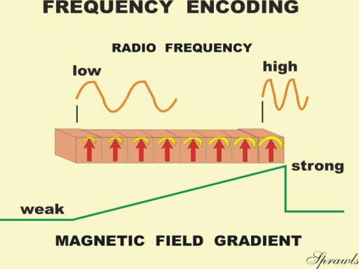 |
In
this example, a gradient is applied along the row. The magnetic field strength
is increased from left to right. This means that each voxel is located in a
different field strength and is resonating at a frequency different from all of
the others. The resonant and RF signal frequencies increase from the left to
right as shown.
The frequency-encoding gradient is on at the time of the echo event when
the signals are actually being produced. The signals from all of the voxels in a
slice are produced simultaneously and are emitted from the body mixed together
to form a composite signal at the time of the echo event. The individual signals
will be separated later by the reconstruction process to form the voxels.
Phase is a relationship between one signal and another, as illustrated in Figure 9-8.
| Figure 9-8. The concept of phase between the signals from two voxels. |
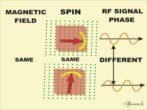 |
Here we
see two voxels producing RF signals. The transverse magnetization is spinning at
the same rate and producing signals that have the same frequency. However, we
notice that one signal is more advanced in time or is out of step with the
other. In other words, the two signals are out of phase. The significance of
voxel-to-voxel phase in MRI is that it can be used to separate signals and
create one dimension in the image.
A phase difference is created by temporarily changing the spinning rate
of the magnetization of one voxel with respect to another. This happens when the
two voxels are located in magnetic fields of different strengths. This can be
achieved by turning on a gradient, as shown in Figure 9-9.
|
Figure 9-9.
Phase-encoding produced by turning on a gradient for a short time, and
then turning it off. The phase difference remains. |
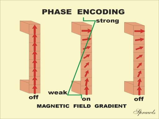 |
Let us begin the process of phase encoding by considering the column of
voxels shown in the illustration. We are assuming that all voxels have the same
amount of transverse magnetization and that the magnetization is spinning
in-phase at the time just prior to the phase-encoding process.
When the phase-encoding gradient is turned on, we have the condition
illustrated with the center column of voxels. The strength of the magnetic field
is increasing from bottom to top. Therefore, the magnetization in each voxel is
spinning at a different rate with the speed increasing from bottom to top. This
causes the magnetization from voxel to voxel to get out of step or produce a
phase difference. The phase-encoding gradient remains on for a short period of
time and then is turned off. This leaves the condition represented by the column
of voxels on the right. This is the condition that exists at the time of the
echo event when the signals are actually produced. As we see, the signals from
the individual voxels are different in terms of their phase relationship. In
other words, the signals are phase-encoded. All of the signals are emitted at
the same time and mixed together as a composite echo signal. Later, the
reconstruction process will sort the individual signal components.
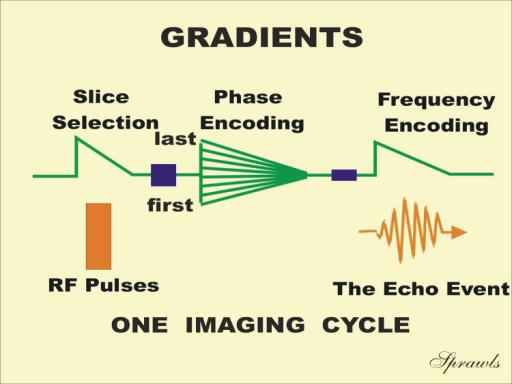
Phase-encoding is the second function performed by a gradient during each cycle, as shown in Figure 9-10.
|
Figure 9-10. The
relationship of the three gradient actions—slice selection,
phase-encoding, and frequency-encoding—to each other and to the RF
pulses and signals. They are applied in different directions. |
 |
During
each pass through an imaging cycle, the phase-encoding gradient is stepped to a
slightly different value.
The signals acquired with each phase-encoding gradient strength
fills one row of k space. This is a very important point that should be
emphasized: Each row of k space is reserved for signals with a specific
degree of phase-encoding. The degree of phase-encoding is determined by the
strength and duration of the phasing gradient applied during each cycle.
Therefore, the phase-encoding process must be repeated depending on the size of
k space and that is determined by the image matrix size in the phase-encoded
direction.
One MRI phase-encoding step produces a composite signal from all voxels
within a slice. The difference from one step to another is that individual voxel
signals have a different phase relationship within the composite signal.
To reconstruct an image by the conventional 2-D Fourier transformation
method, one composite signal, or phase-encoded step, must be collected for each
voxel to be created in the phase-encoding direction. Therefore, the minimum
number of steps required to produce an image is determined by the size of the
image matrix and k space. It takes 256 phase-encoding steps to produce an image
with a 256 ´ 256 matrix.
We have
seen that various gradients are turned on and off at specific times within each
imaging cycle. The relationship of each gradient to the other events during an
imaging cycle is shown in Figure 9-10. The three gradient activities are:
2. The
phase-encoding gradient is turned on for a short period in each cycle to produce
a phase difference in one dimension of the image. The strength of this gradient
is changed slightly from one cycle to another to fill the different rows of k
space needed to form the image.
3. The
frequency-encoding gradient is turned on during the echo event when the signals
are actually emitted by the tissue. This causes the different voxels to emit
signals with different frequencies.
Because of the combined action of the three gradients, the individual
voxels within each slice emit signals that are different in two respects—they
have a phase difference in one direction and a frequency difference in the
other. Although these signals are emitted at the same time, and picked up by the
imaging system as one composite signal at the time of the echo event in each
cycle, the reconstruction process can sort the signals into the respective
components and display them in the correct image pixel locations.
The next
major step in the creation of an MR image is the reconstruction process.
Reconstruction is the mathematical process performed by the computer that
converts the collected signals in k space into an actual image. There are
several reconstruction methods, but the one used for most clinical applications
is the 2-D Fourier transformation.
It is a mathematical procedure that can sort a composite signal into
individual frequency and phase components. Since each voxel in a row emits a
different signal frequency and each voxel in a column a different phase, the
Fourier transformation can determine the location of each signal component and
direct it to the corresponding pixel.
Let us now use the concept illustrated in Figure 9-11 to summarize the spatial characteristics of the MR image.
|
Figure 9-11. The concept of signal encoding
(addressing) and image reconstruction (sorting and delivery). |
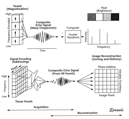 |
We will
use a postal analogy for this purpose.
In the image each column of pixels has a phase address corresponding to
different street names. Each row of pixels has a frequency address corresponding
to house numbers. Therefore, each individual pixel has a unique address
consisting of a combination of frequency and phase values analogous to a street
name and house number.
The frequency- and phase-encoding process during acquisition “writes” an
address on the signal from each voxel. These signals are mixed together and
collected in a “post-office” called k space. The signals (“mail”) are then
sorted by the Fourier transform process and hopefully delivered to the correct
pixel address in the image.
In Chapter 14 we will see that if a voxel of tissue moves during the
acquisition process, it might not receive the correct phase address and the
signal will be delivered to the wrong pixel. This creates ghost images and
streak artifacts in the phase-encoded direction.
The
chemical-shift artifact is caused by the difference in signal frequency between
tissues containing water and fat. When it is present in an image, signals from
the water components and fat will be offset by a few pixels. We will see how
this is controlled in Chapter 14.
Mind Map Summary
Spatial Characteristics of the Magnetic Resonance Image
Two methods can be selected to produce the slices. The most common
method, 2-D multiple slice acquisition, applies a gradient so that an individual
slice is tuned to a resonant frequency different from the other slice positions.
This gradient is turned on when the RF pulses are applied. Therefore, only the
tissue in a specific slice is excited and goes through the process to produce
signals. An alternate method, 3-D volume acquisition, uses phase-encoding to
produce slices. It is generally capable of producing thinner, more contiguous
slices.
Two different methods are used to cut a slice into voxels. Phase-encoding
is used in one direction, and frequency-encoding in the other. Phase-encoding is
produced by applying a gradient to the transverse magnetization during each
imaging cycle. To produce sufficient phase-encoding information to permit image
reconstruction, many different phase-encoding gradient strengths must be used.
In the typical imaging procedure the phase-encoding gradient strength is changed
from cycle to cycle. The strength of the phase-encoding gradient, in effect,
directs the signal data into a specific row of k space. All the rows of k space
must be filled with data before the image reconstruction can be performed. The
number of rows of k space is one of the factors that determine how many imaging
cycles must be used, which, in turn, affects image acquisition time.
Frequency-encoding is produced by applying a gradient at the time of the
echo event during each cycle.