Chapter 6
Spin Echo Imaging Methods
|
|
Chapter 6
|
| Link to Book Table of Contents | Chapter Contents Shown Below |
| Introduction And Overview | The Spin Echo Process | RF Pulse Sequence |
| The Spin Echo Method | Proton Density (PD) Contrast |
T1 Contrast |
|
T2 Contrast |
Multiple Spin Echo | Inversion Recovery |
|
T1 Contrast |
||
Spin
echo is the name of the process that uses an RF pulse to produce the echo event.
It is also the name for one of the specific imaging methods within the spin echo
family of imaging methods; all of which use the spin echo process. We will first
discuss the spin echo process and see how an RF pulse can produce an echo event
and signal and then consider the spin echo methods.
The
decay of transverse magnetization (i.e., relaxation) occurs because of dephasing
among individual nuclei, as described in Chapter 4.
Let us recall that two basic conditions are required for transverse
magnetization: (1) the magnetic moments of the nuclei must be oriented in the
transverse direction, or plane, and (2) a majority of the moments must be in the
same direction within the transverse plane. When a nucleus has a transverse
orientation, it is actually precessing or rotating around an axis that is
parallel to the magnetic field.
After the application of a 90˚ excitation pulse, the nuclei have a
transverse orientation and are precessing together, or in-phase, around the
magnetic field axis. This is the normal precession discussed earlier but flipped
into the transverse plane. However, within an individual voxel some nuclei
precess or spin faster than others. After a short period of time, the nuclei are
not spinning in-phase. As the directions of the nuclei begin to spread, the
magnetization of the tissue decreases. A short time later, the nuclei are
randomly oriented in the transverse plane; there is no transverse magnetization.
The two factors that contribute to the de-phasing of the nuclei and the
resulting transverse relaxation will now be reviewed again here. One is an
exchange among the spinning nuclei (spin-spin interactions), which results in
relatively slow dephasing and loss of magnetization. The rate at which this
occurs is determined by characteristics of the tissue. It is this dephasing
activity that is characterized by the T2 values and the source of contrast that
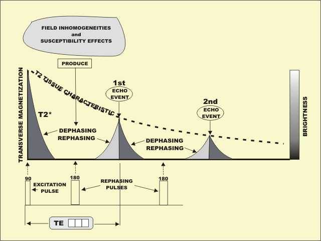
we want to capture in T2 images. A second factor, which produces relatively
rapid dephasing of the nuclei and loss of transverse magnetization, is the
inhomogeneity of the magnetic field. Even within a small volume of tissue, the
field inhomogeneities are sufficient to produce rapid dephasing. This effect,
which is generally unrelated to the T2 characteristics of the tissue, tends to
mask the true relaxation characteristics of the tissue. In other words, the
actual transverse magnetization relaxes much faster than the tissue
characteristics would indicate. We remember that this real relaxation time is
designated as T2*. The value of T2* is always much less than the tissue T2
value. As a result, the transverse magnetization disappears before T2 contrast
can be formed.
We are about to discover that spin echo is a process for recovering the
lost transverse magnetization and making it possible to produce images of the
three tissue characteristics, including T2.
An RF signal is produced whenever there is transverse magnetization.
Immediately after an excitation pulse, a so-called free induction decay (FID)
signal is produced. The intensity of this signal is proportional to the level of
transverse magnetization. Both decay rather rapidly because of the magnetic
field inhomogeneities just described. The FID signal is not used in the spin
echo methods. It is used in the gradient echo methods to be described in Chapter
7.
The spin echo process is used to compensate for the dephasing and rapid
relaxation caused by the field inhomogeneities and to restore the magnetization
to the level that depends only on the tissue T2 characteristics. The sequence of
events in the spin echo process is illustrated in Figure 6-1.
|
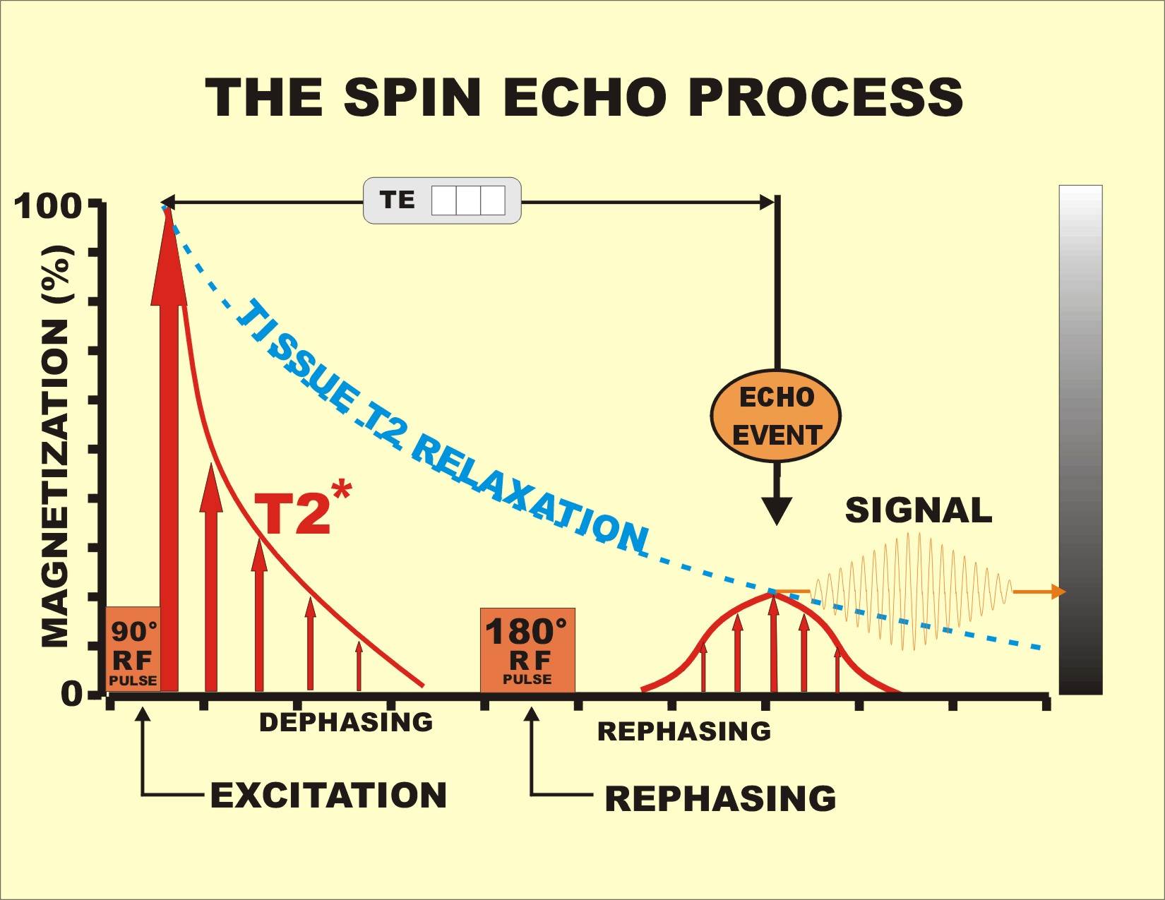
Figure 6-1. The
spin echo process showing the use of a 180° pulse to rephase the protons
and to produce an echo event. |
|
Transverse magnetization is produced with a 90˚ RF excitation pulse that flips
the longitudinal magnetization into the transverse plane. Immediately following
the RF pulse, each voxel is magnetized in the transverse direction. However,
because of the local magnetic field inhomogeneities within each voxel, the
protons precess at different rates and quickly slip out of phase. This produces
the rapid decay characterized by T2* and the associated FID signal. At this time
the protons are still rotating in the transverse plane, but they are out of
phase.
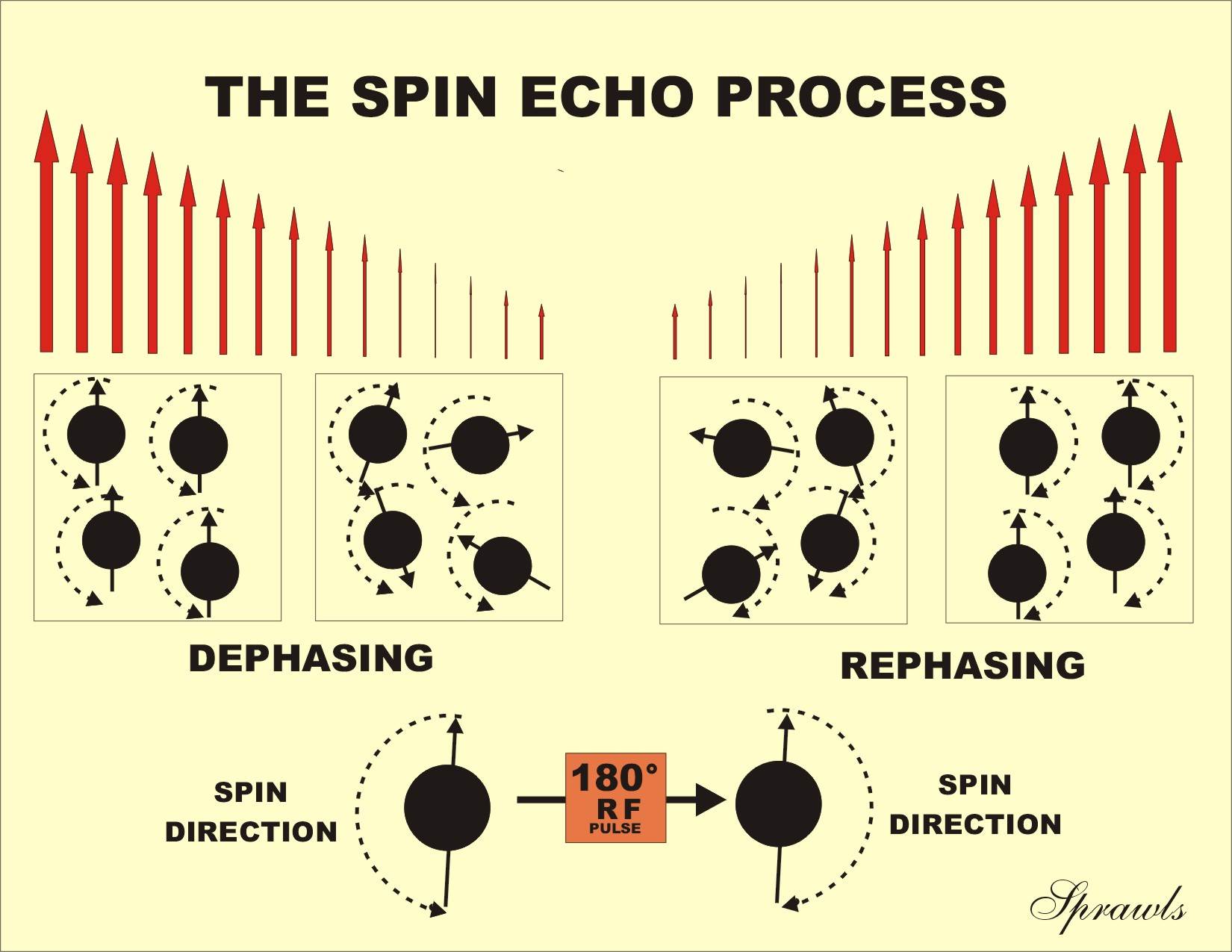
If a 180° pulse is applied to the tissue containing these protons, it flips the protons around an axis in the transverse plane; this reverses their direction of rotation as illustrated in Figure 6-2.
|
Figure 6-2. The 180° pulse sets up the protons so that they rephase. |
|
This
causes the fast protons to be located behind the slower ones. As the faster
protons begin to catch up with the slower ones, they regain a common alignment,
or come back into phase. This, in turn, causes the transverse magnetization to
reappear and form the echo event. However, the magnetization does not grow to
the initial value because the relaxation (dephasing) produced by the tissue is
not reversible. The rephasing of the protons causes the magnetization to build
up to a level determined by the T2 characteristics of the tissue. As soon as the
magnetization reaches this maximum, the protons begin to move out of phase
again, and the transverse magnetization dissipates. Another 180˚ pulse can be
used to produce another rephasing. In fact, this is what is done in multi-echo
imaging and will be described later in this chapter.
The
different imaging methods are produced by the type (flip angle) and time
intervals between the applied RF pulses. The basic pulse sequence for the spin
echo method is shown in Figure 6-3. Each cycle begins with a 90° excitation
pulse that produces the initial transverse magnetization and a later 180° pulse
that rephases the protons to produce the echo event.
|
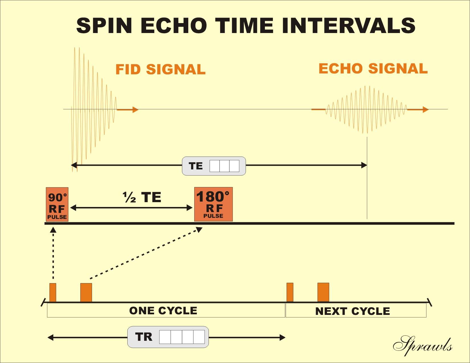
Figure 6-3. The RF pulses and time intervals in a spin echo imaging cycle. |
|
The time between the initial excitation and the echo signal is TE. This
is controlled by adjusting the time interval between the 90˚ and the 180˚
pulses, which is 1/2 TE.
This
method can be used to produce images of the three basic tissue characteristics:
PD, T1, and T2. The sensitivity to a specific characteristic is determined by
the values selected for the two time intervals or imaging factors, TR and TE.
The process of creating images with the three types of contrast (PD, T1,
and T2) described in the last chapter was a description of the spin echo method.
There we saw that the type of image that was produced depended on the values
selected for the two protocol factors, TR and TE. We will now review that
process with a few more details specifically as it applies to the spin echo
method.
PD
contrast develops as the longitudinal magnetization approaches its maximum,
which is determined by the PD of each specific tissue. Therefore, relatively
long TR values are required to produce a PD-weighted image. Short TE values are
generally used to reduce T2 contrast contamination and to maintain a relatively
high signal intensity.
To
produce image contrast based on T1 differences between tissues, two factors must
be considered. Since T1 contrast develops during the early growth phase of
longitudinal magnetization, relatively short TR values must be used to capture
the contrast. The second factor is to preserve the T1 contrast during the time
of transverse relaxation. The basic problem is that if T2 contrast is allowed to
develop, it generally counteracts T1 contrast. This is because tissues with
short T1 values usually have short T2 values. The problem arises because tissues
with short T1s are generally bright, whereas tissues with short T2s have reduced
brightness when T2 contrast is present. T2 contrast develops during the TE time
interval. Therefore, a T1-weighted image is produced by using short TR values
and short TE values.
The
first step in producing an image with significant T2 contrast is to select a
relatively long TR value. This minimizes T1 contrast contamination and the
transverse relaxation process begins at a relatively high level of
magnetization. Long TE values are then used to allow T2 contrast time to
develop.
The spin
echo method is the only method that produces true T2 contrast. That is because
it is able to rephase the protons and remove the T2* effect.
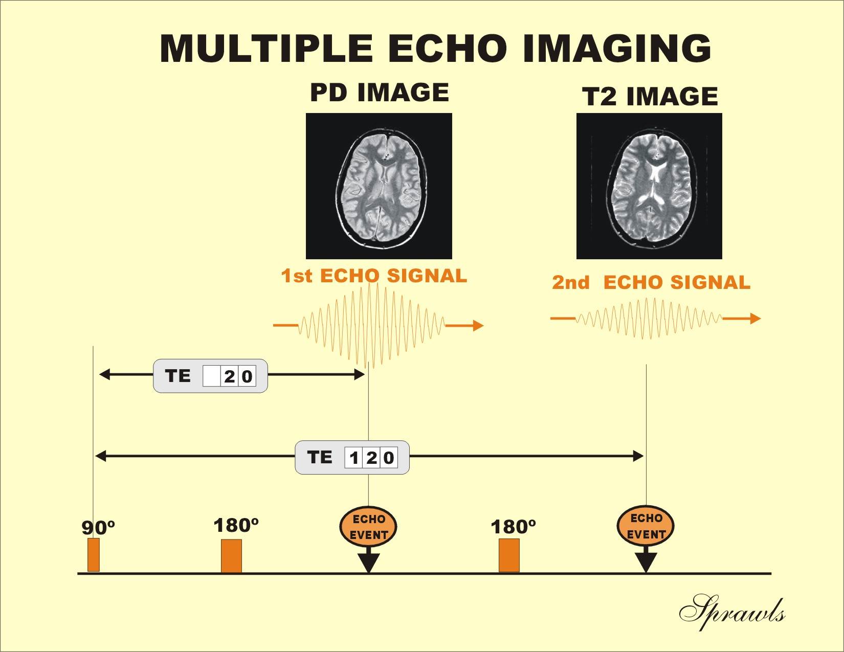
It is possible to produce a series of echo events within one cycle as illustrated in Figure 6-4.
|
Figure 6-4. A
multiple spin echo imaging that produces both a PD and T2 image in the
same acquisition. |
|
This is
done by applying several 180° pulses after each 90° excitation pulse. The
advantage is that echo events with different TE values are produced in one
acquisition cycle. Separate images are formed for each TE value. This makes it
possible to create both a PD image (short TE) and a T2 image (long T2) in the
same acquisition.
Table 6-1 summarizes the combination of TR and TE values used to produce
the three basic image types with the spin echo method. Optimum values of TR and
TE for a specific protocol might vary because of considerations for other
factors such as image acquisition time, number of slices, etc.
Table
6-1. Selection of TR and TE values to produce the three image types with spin
echo method. Values shown are typical but can be varied to some extent to
accommodate specific imaging conditions.
|
|
T1 Image |
PD Image |
T2 Image |
|
TR |
Short |
Long |
Long |
|
TE |
Short |
Long |
Long |
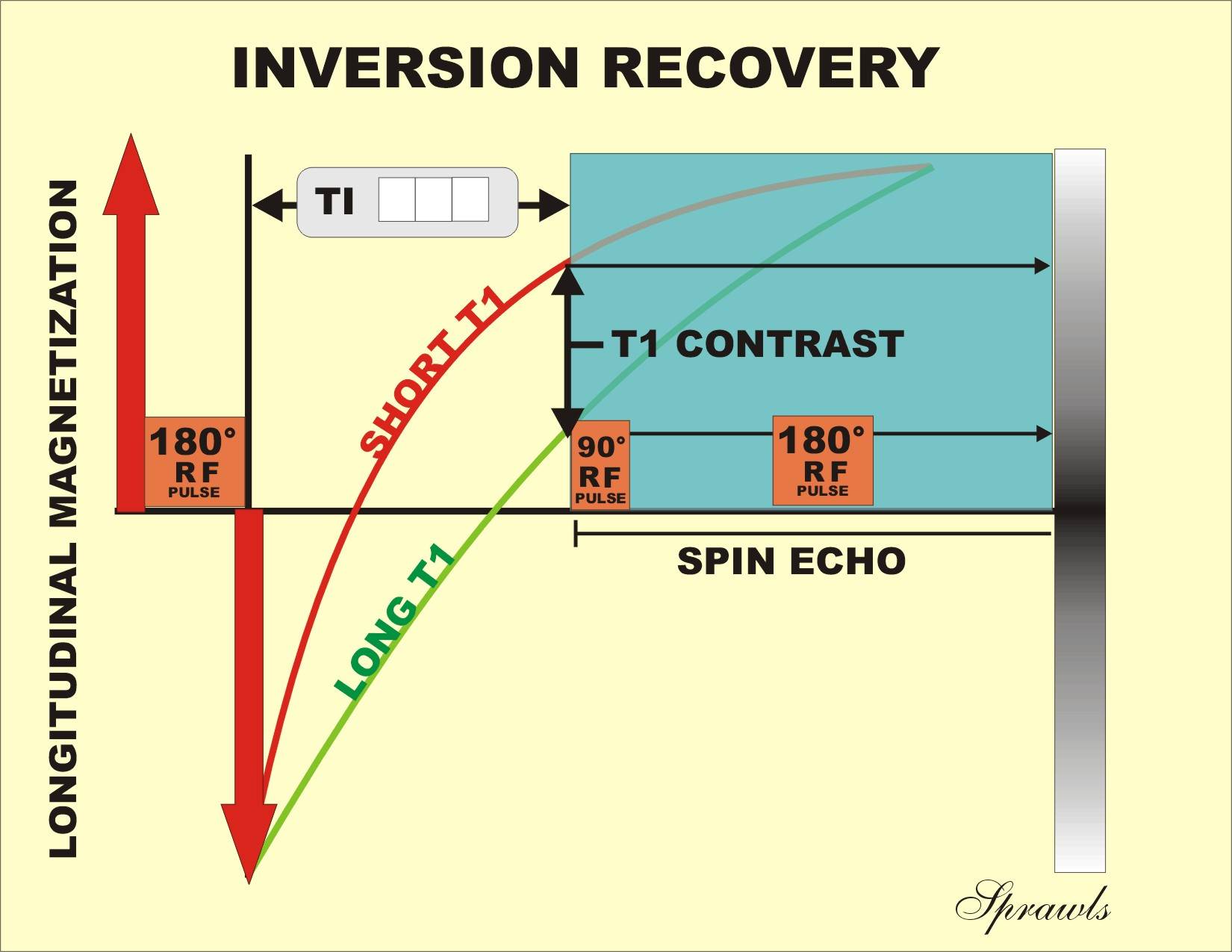
Inversion recovery is a spin echo imaging method used for several specific purposes. One application is to produce a high level of T1 contrast and a second application is to suppress the signals and resulting brightness of fat and fluids. The inversion recovery pulse sequence is obtained by adding an additional 180˚ pulse to the conventional spin echo sequence, as shown in Figure 6-5.
|
Figure 6-5. The
inversion recovery method with TI set to produce an image with high T1
contrast. |
|
The
pulse is added at the beginning of each cycle where it is applied to the
longitudinal magnetization carried over from the previous cycle. Each cycle
begins as the 180˚ pulse inverts the direction of the longitudinal
magnetization. The regrowth (recovery) of the magnetization starts from a
negative (inverted) value, rather than from zero, as in the spin echo method.
The inversion recovery method, like the spin echo method, uses a 90°
excitation pulse to produce transverse magnetization and a final 180° pulse to
produce a spin echo signal. That is why it is classified as one of the spin
echo, rather than gradient echo, methods. An additional time interval is
associated with the inversion recovery pulse sequence. The time between the
initial 180˚ pulse and the 90˚ pulse is designated the Time after Inversion
(TI). It can be varied by the operator and used as a contrast control.
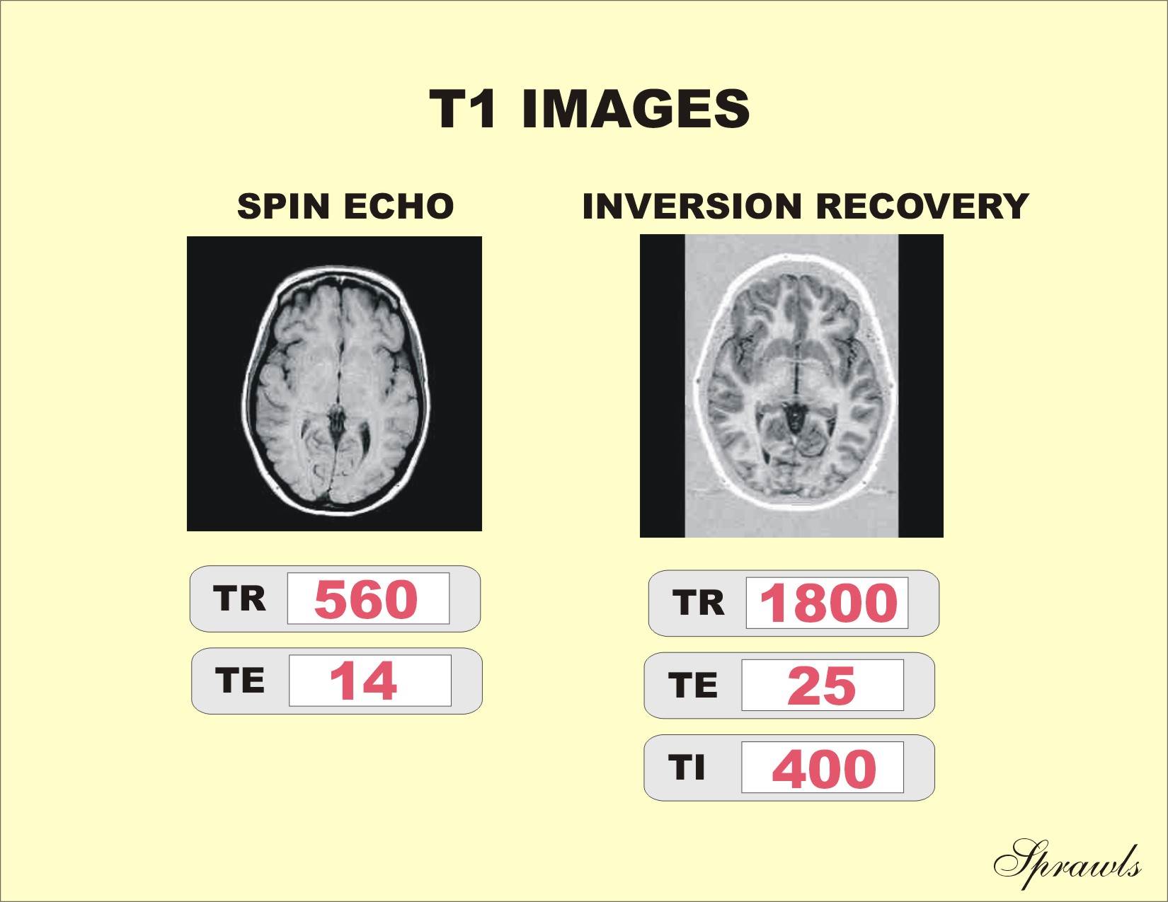
The principal characteristic of many inversion recovery images is high T1 contrast. This occurs because the total longitudinal relaxation time is increased because it starts from the inverted state. There is more time for the T1 contrast to develop. A T1 image produced by the inversion recovery method is compared to one produced by the spin echo method in Figure 6-6.
|
Figure 6-6.
Comparison of T1 images produced by spin echo and inversion recovery
methods. |
|
Notice
the significant difference in contrast. The use of the inversion method for
other applications will be discussed in Chapter 8.
Spin Echo Imaging Methods
Spin echo is a technique used to produce an echo event by applying a 180˚
RF pulse to the dephased transverse magnetization. This compensates for the
dephasing produced by field inhomogeneities and makes it possible to produce
images that show the T2 characteristics of tissue. The time to the echo event,
TE, is a protocol factor that can be adjusted to produce different weightings to
the T2 contrast. When a short TE value is selected, the T2 effect is reduced,
and the resulting image will be either a PD or T1-weighted image, depending on
the selected TR value.
It is possible to use a series of 180˚ RF pulses within one cycle to
produce multiple echo events, each with a different TE value. Both PD and
T2-weighted images can be acquired in the same acquisition.