
Chapter 2
M
|
|
Chapter 2 |
| Link to Book Table of Contents | Chapter Contents Shown Below |
|
Mind Map Summary |
||
The MRI
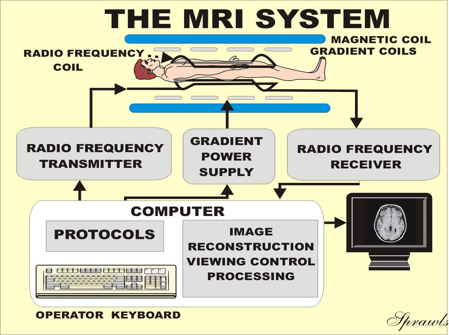
system consists of several major components, as shown in Figure 2-1. At this
time we will introduce the components and indicate how they work together to
create the MR image. The more specific details of the image forming process will
be explained in later chapters.
|
Figure 2-1. The major
components of the |
 |
The heart of the MRI system is a large magnet that produces a very strong
magnetic field. The patient’s body is placed in the magnetic field during the
imaging procedure. The magnetic field produces two distinct effects that work
together to create the image.
When the
patient is placed in the magnetic field, the tissue becomes temporarily
magnetized because of the alignment of the protons, as described previously.
This is a very low-level effect that disappears when the patient is removed from
the magnetic field. The ability of MRI to distinguish between different types of
tissue is based on the fact that different tissues, both normal and pathologic,
will become magnetized to different levels or will change their levels of
magnetization (i.e., relax) at different rates.
The
magnetic field also causes the tissue to “tune in” or resonate at a very
specific radio frequency. That is why the procedure is known as magnetic
resonance imaging. It is actually certain nuclei, typically protons, within
the tissue that resonate. Therefore, the more comprehensive name for the
phenomenon that is the basis of both imaging and spectroscopy is nuclear
magnetic resonance (NMR).
In the presence of the strong magnetic field the tissue resonates in the
RF range. This causes the tissue to function as a tuned radio receiver and
transmitter during the imaging process. The production of an MR image involves
two-way radio communication between the tissue in the patient’s body and the
equipment.
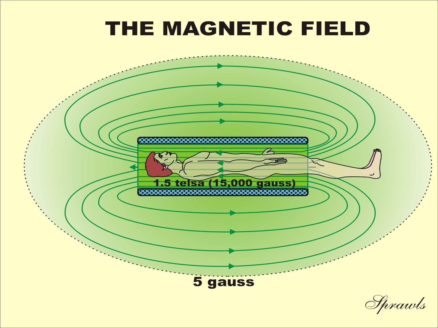
Figure
2-2 shows the general characteristics of a typical magnetic field. At any point
within a magnetic field, the two primary characteristics are field direction
and field strength.
|
Figure 2-2. The magnetic field produced by
superconducting magnets. |
 |
High homogeneity is obtained by the process of shimming, as described
later.
There are two requirements for superconductivity. The conductor or wire
must be fabricated from a special alloy and then cooled to a very low
temperature. The typical magnet consists of small niobium-titanium (Nb-Ti) wires
imbedded in copper. The copper has electrical resistance and actually functions
as an insulator around the Nb-Ti superconductors.
During normal operation the electrical current flows through the
superconductor without dissipating any energy or producing heat. If the
temperature of the conductor should ever rise above the critical superconducting
temperature, the current begins to produce heat and the current is rapidly
reduced. This results in the collapse of the magnetic field. This is an
undesirable event known as a quench. More details are given in Chapter 15
on safety. Superconducting magnets are cooled with liquid helium. A disadvantage
of this magnet technology is that the coolant must be replenished periodically.
A characteristic of most superconducting magnets is that they are in the
form of cylindrical or solenoid coils with the strong field in the internal
bore. A potential problem is that the relatively small diameter and the long
bore produce claustrophobia in some patients. Superconducting magnetic design is
evolving to more open patient environments to reduce this concern.
A
resistive type magnet is made from a conventional electrical conductor such as
copper. The name “resistive” refers to the inherent electrical resistance that
is present in all materials except for superconductors. When a current is passed
through a resistive conductor to produce a magnetic field, heat is also
produced. This limits this type of magnet to relatively low field strengths.
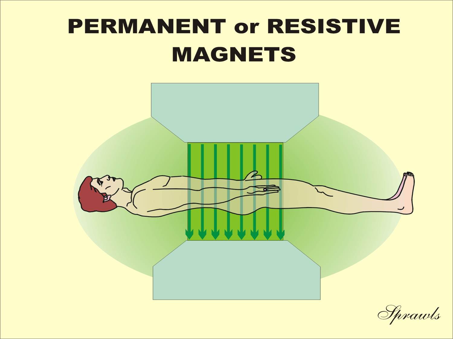
Both resistive and permanent magnets are usually designed to produce
vertical magnetic fields that run between the two magnetic poles, as shown in
Figure 2-3. Possible advantages include a more open patient environment and less
external field than superconducting magnets.
|
Figure 2-3. The magnetic field produced by typical
resistive or permanent magnets. |
 |
|
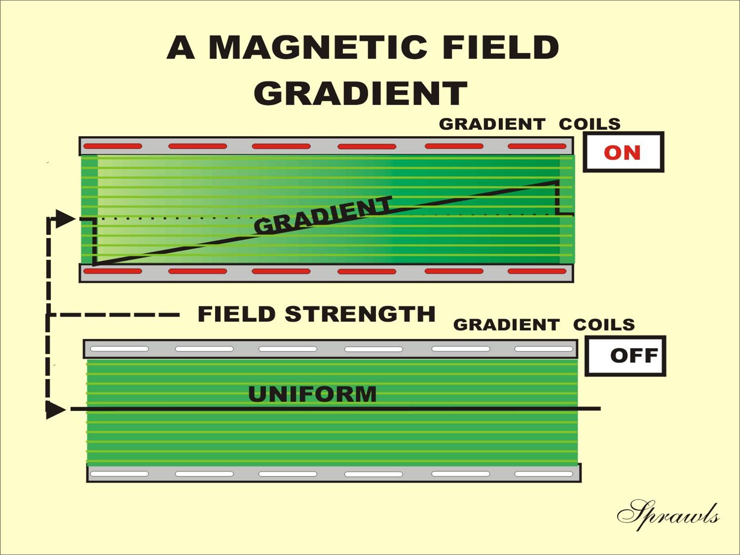
Figure 2-4. A magnetic field gradient produced by a
current in the gradient cell. |
 |
Gradients are designed to minimize eddy currents either with special
gradient shielding or electrical circuits that control the gradient currents in
a way that compensates for the eddy-current effects.
Inhomogeneities are usually produced by magnetically susceptible
materials located in the magnetic field. The presence of these materials
produces distortions in the magnetic field that are in the form of
inhomogeneities. This can occur in both the internal and external areas of the
field. Each time a different patient is placed in the magnetic field, some
inhomogeneities are produced. There are many things in the external field, such
as building structures and equipment, that can produce inhomogeneities. The
problem is that when the external field is distorted, these distortions are also
transferred to the internal field where they interfere with the imaging process.
Inhomogeneities produce a variety of problems that will be discussed later.
It is not possible to eliminate all of the sources of inhomogeneities.
Therefore, shimming must be used to reduce the inhomogeneities. This is done in
several ways. When a magnet is manufactured and installed, some shimming might
be done by placing metal shims in appropriate locations. Magnets also contain a
set of shim coils. Shimming is produced by adjusting the electrical currents in
these coils. General shimming is done by the engineers when a magnet is
installed or serviced. Additional shimming is done for individual patients. This
is often done automatically by the system.
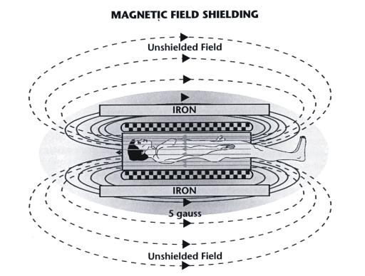
It is a common practice to reduce the size of the external field by
installing shielding as shown in Figure 2-5. The principle of magnetic field
shielding is to provide a more attractive return path for the external field as
it passes from one end of the magnetic field to the other. This is possible
because air is not a good magnetic field conductor and can be replaced by more
conductive materials, such as iron. There are two types of shielding: passive
and active.
|
Figure 2-5. The principle of magnetic field
shielding. |
 |
The MRI process uses RF signals to transmit the image from the patient’s
body. The RF energy used is a form of non-ionizing radiation. The RF pulses that
are applied to the patient’s body are absorbed by the tissue and converted to
heat. A small amount of the energy is emitted by the body as signals used to
produce an image. Actually, the image itself is not formed within and
transmitted from the body. The RF signals provide information (data) from which
the image is reconstructed by the computer. However, the resulting image is a
display of RF signal intensities produced by the different tissues.
|
Figure 2-6. The three types of RF coils (body,
head, and surface) that are the antennae |
 |
Surface
coils are used to receive signals from a relatively small anatomical region to
produce better image quality than is possible with the body and head coils.
Surface coils can be in the form of single coils or an array of several coils,
each with its own receiver circuit operated in a phased array
configuration. This configuration produces the high image quality obtained from
small coils but with the added advantage of covering a larger anatomical region
and faster imaging.
The transmitter actually consists of several components, such as RF
modulators and power amplifiers, but for our purposes here we will consider it
as a unit that produces pulses of RF energy. The transmitters must be capable of
producing relatively high power outputs on the order of several thousand watts.
The actual RF power required is determined by the strength of the magnetic
field. It is actually proportional to the square of the field strength.
Therefore, a 1.5 T system might require about nine times more RF power applied
to the patient than a 0.5 T system. One important component of the transmitter
is a power monitoring circuit. That is a safety feature to prevent excessive
power being applied to the patient’s body, as described in Chapter 15.
A short
time after a sequence of RF pulses is transmitted to the patient’s body, the
resonating tissue will respond by returning an RF signal. These signals are
picked up by the coils and processed by the receiver. The signals are converted
into a digital form and transferred to the computer where they are temporarily
stored.
An area can be shielded against external RF signals by surrounding it
with an electrically conducted enclosure. Sheet metal and copper screen wire are
quite effective for this purpose.
The principle of RF shielding is that RF signals cannot enter an
electrically conductive enclosure. The thickness of the shielding is not a
factor—even thin foil is a good shield. The important thing is that the room
must be completely enclosed by the shielding material without any holes. The
doors into imaging rooms are part of the shielding and should be closed during
image acquisition.
Protocols stored in the computer control the acquisition process. The
operator can select from many preset protocols for specific clinical procedures
or change protocol factors for special applications.
The RF
signal data collected during the acquisition phase is not in the form of an
image. However, the computer can use the collected data to create or
“reconstruct” an image. This is a mathematical process known as a Fourier
transformation that is relatively fast and usually does not have a significant
effect on total imaging time.
In many applications it is desirable to process the reconstructed images
to change their characteristics, to reformat an image or set of images, or to
change the display of images to produce specific views of anatomical regions.
These post-processing (after reconstruction) functions are performed by a
computer. In some MRI systems some of the post processing is performed on a
work-station computer that is in addition to the computer contained in the MRI
system.
Magnetic Resonance Imaging System Components
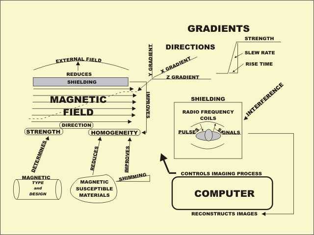
The
magnetic resonance imaging system consists of several major components that
function together to produce images. During the image acquisition process the
patient’s body is placed in a strong magnetic field. At each point, the magnetic
field has a specific direction. This direction is used as a reference for
expressing the direction of tissue magnetization. The strength of a magnetic
field is determined by the type and design of the magnet. Superconducting
magnets can produce strong magnetic fields. Resistive and permanent magnets are
limited to relatively weak field strengths. The homogeneity, or uniformity of
field strength is necessary for good imaging.
Homogeneity is reduced by magnetically susceptible materials that come
into the field and produce distortions. This can occur in both the external
field and within a patient’s body. Shimming is the process of adjusting the
magnetic field to make it more homogeneous. This can be achieved by passive
shims that are added when a magnet is installed and with active shimming
produced by adjusting the currents in the shimming coils.
Shielding of the magnetic field reduces the size and strength of the
external magnetic field and also improves homogeneity by protecting from
interference caused by objects in the external field area.
A
gradient is an intentional variation in magnetic field strength that is produced
by the gradient coils. There are three basic gradient coils that are oriented to
produce gradients in the three orthogonal directions. Gradients perform several
functions during the image acquisition process. An important characteristic of a
gradient, especially for some advanced image procedures, is its strength and how
fast it can be turned on and off.
The MRI process consists of an exchange of RF pulses and signals between
the equipment and the patient’s body. This is done through the RF coils that
serve as the antenna for transmitting the pulses and receiving the signals. It
is necessary to shield the imaging area by enclosing it in a conductive metal
(copper) room to block external RF interference.
The imaging process is controlled by information stored in a computer.
The protocols programmed into the computer and selected by the operator guide
the imaging process and determine the characteristics of the images. The RF
signals collected from the patient’s body during the acquisition process are
used by the computer to reconstruct the image.